¶ Introduction
Banana Pi BPI-AI2N System-on-Module (SoM) and BPI-AI2N carrier board are open-source hardware solutions designed to leverage the advanced capabilities of the RZ/V2N Vision AI MPU. It supports 8GB memory, 32GB emmc, dual gigabit ethernet ports, 2x USB3 interface.
¶ Specifications
-
SoC – Renesas RZ/V2N quad-core 64bit Arm Cortex-A55 processor @ up to 1.8 GHz with Mali-G31 GPU
-
System Memory – 8GB LPDDR4
-
Storage – 32GB eMMC flash, MicroSD slot
-
Video Output – MIPI DSI to hdmi connector, up to 1080p
-
Connectivity – Dual Gigabit Ethernet
-
USB – 2x USB 3.0 ports,1x USB-C port
-
Expansion – 40-pin header with 28x GPIO, UART, I2C, SPI, PWM, and power signal (+5V, +3.3V, GND).
-
Debugging – USB Type-C debug header
-
Power Supply – 12V @3A DC adapter
¶ Armbian Linux
¶ Prepare
-
Linux image support SDcard or EMMC bootup.
-
It’s recommended to use A1 rated cards, 16GB at least.
-
Download latest Linux Image, and confirm that the checksum is correct.
-
Default login: pi/bananapi or root/bananapi
¶ Install Image to SDcard
-
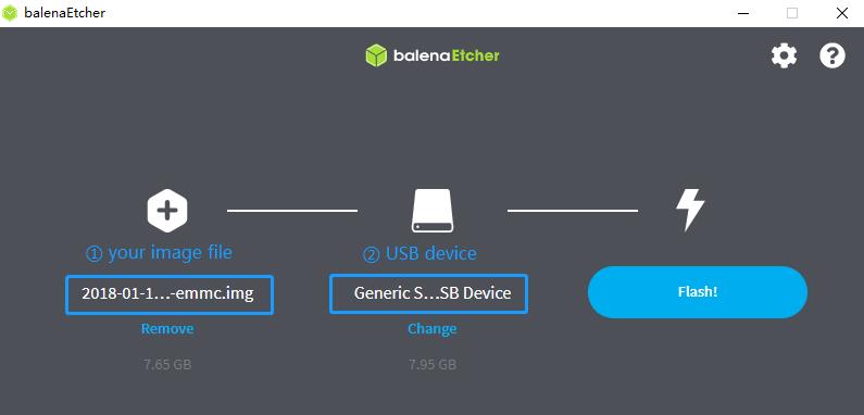
Install Image with Balena Etcher on Windows, Linux and MacOS.
Balena Etcher is an opensource GUI flash tool by Balena, Flash OS images to SDcard or USB drive.
-
Click on "Flash from file" to select image.
-
Click on "Select target" to select USB device.
-
Click on "Flash!" Start burning.
-
-
Install Image with Balena Cli on Windows, Linux and MacOS.
Balena CLI is a Command Line Interface for balenaCloud or openBalena. It can be used to flash linux image. Download the installer or standalone package from balena-io and install it correctly to your PC, then you can use the "local flash" command option of balena to flash a linux image to sdcard or usb drive.
$ sudo balena local flash xxx-bpi-ai2n-xxx.img.xz $ sudo balena local flash xxx-bpi-ai2n-xxx.img.xz --drive /dev/sdX $ sudo balena local flash xxx-bpi-ai2n-xxx.img.xz --drive /dev/sdX --yes -
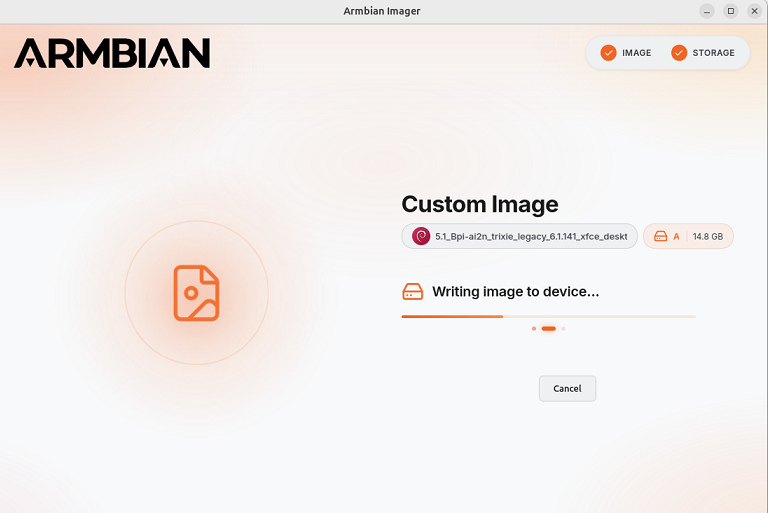
Install Image with Armbian Imager on Windows, Linux and MacOS.
Armbian Imager is an open-source imaging tool for installing Armbian OS.
For un-official board images, please select Use Custom Image→Browse and select the local image file→Select the target storage→Erase&Flash.
-
Install Image with dd command on Linux
umount SDcard device /dev/sdX partition if mounted automatically.
$ sudo apt-get install xz-utils pv
$ sudo sh -c 'xzcat xxx-bpi-ai2n-xxx.img.xz | pv | dd of=/dev/sdX bs=1M status=progress && sync'
¶ Install Image to eMMC
-
Prepare a SDcard with Linux image flashed and bootup board with this SDcard.
-
Copy target image to udisk, plug the udisk to board and mount it.
-
Install image to emmc.
-
Write with dd command, umount mmcblk0p1 and mmcblk0p2 partition if mounted automatically.
$ sudo apt-get install xz-utils pv $ sudo sh -c 'xzcat xxx-bpi-ai2n-xxx.img.xz | pv | dd of=/dev/sdX bs=1M status=progress && sync' -
another way is transfer the live running Armbian system from an SD card to internal storage devices such as eMMC. It prepares the target storage, copies the active system, adjusts bootloader settings, and ensures the system can boot independently without requiring reinstallation.
$ sudo armbian-config --cmd STO001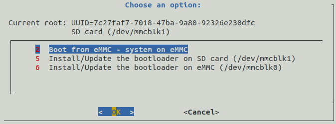
-
¶ Build Armbian Source Code
$ git clone -b bpi-v25.8.1 https://github.com/BPI-SINOVOIP/armbian-build.git
$ cd armbian-build
$ ./compile.sh BOARD=bpi-ai2n BRANCH=legacyMore info about armbian build, please refer to Armbian Build Framework Quick Start Guide
¶ First boot
Insert the SD card into a slot and power on the board. The first boot will log you in automatically if you have connected a display via HDMI or if you are connected to the serial console.
After logging in, you will be prompted to change the default password. You will then be asked to create a normal user account that will have sudo permissions. Beware, at this stage the keyboard is using the QWERTY layout. In case you have no wired network connection and there is a wireless adaptor detected, the system will prompt you to connect.
Welcome to Bananapi-Armbian!

Documentation: https://wiki.banana-pi.org/ | Community support: https://forum.banana-pi.org/

IP address:  Network connection timeout!

Create root password: ********
Repeat root password: ********

Warning: Weak password, it is based on a dictionary word!

Choose default system command shell:

1) bash
2) zsh
1

Shell: BASH

Creating a new user account. Press <Ctrl-C> to abort

Please provide a username (eg. your first name): pi
Create user (pi) password: ********
Repeat user (pi) password: ********

Warning: Weak password, it is based on a dictionary word!

Please provide your real name: Pi

Dear Pi, your account pi has been created and is sudo enabled.
Please use this account for your daily work from now on.

Internet connection was not detected.

Connect via wireless? [Y/n] y

Detected wireless networks:

1        NETWORK
2        MY-WIFI

Enter a number of SSID: 2

Enter a password for MY-WIFI: password

Probing internet connection (9)

Detected timezone: Asia/Shanghai

Set user language based on your location? [Y/n] Y

At your location, more locales are possible:

1) bo_CN                    4) ug_CN@latin
2) ug_CN                    5) zh_CN.UTF-8
3) ug_CN@latin              6) Skip generating locales
Please enter your choice:5

Generating locales: zh_CN.UTF-8

 | _ ) __ _ _ _  __ _ _ _  __ _ _ __(_)___ /_\  _ _ _ __ | |__(_)__ _ _ _
 | _ \/ _` | ' \/ _` | ' \/ _` | '_ \ |___/ _ \| '_| '  \| '_ \ / _` | ' \
 |___/\__,_|_||_\__,_|_||_\__,_| .__/_|  /_/ \_\_| |_|_|_|_.__/_\__,_|_||_|
                               |_|
 v25.5.1 for Banana Pi AI2N running Armbian Linux 6.1.107-legacy-renesas

 Packages:     Ubuntu stable (jammy), possible distro upgrade (noble)
 Support:      DIY (custom image)
 IPv4:         (LAN) 10.0.1.5 (WAN) 36.44.140.189

 Performance:

 Load:         35%              Up time:       17 min
 Memory usage: 3% of 7.01G
 CPU temp:     35�°C             Usage of /:   16% of 15G
 RX today:     265 KiB
 Commands:

 Configuration : armbian-config
 Monitoring    : htop

root@bpi-ai2n:/#These settings can be pre-loaded, see Armbian Autoconfig
¶ Armbian-Config
Armbian-Config is a utility for configuring your board, adjusting services, and installing applications. It comes with Armbian images by default.
To start the Armbian configuration utility, use the following command:
$ sudo armbian-config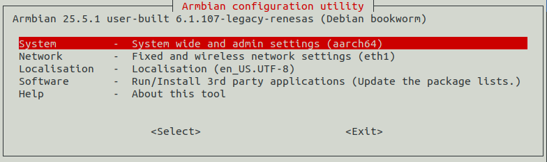
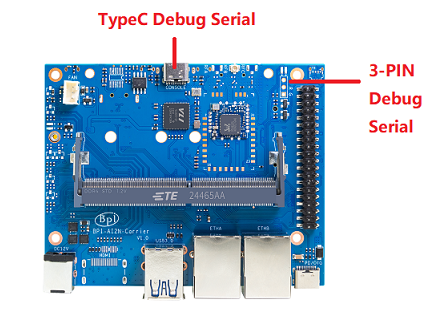
¶ Debug Serial
The board has two debug serial interfaces:
-
Type-C interface. Can be connected to a PC using a regular USB Type-C cable without Linux or Windows specific driver install, and baudrate is 115200.
-
Three pin header interface. A standard 3.3V TTL-level UART port, requires a USB to TTL serial cable (such as CP2102, PL2303, CH340, etc.) to connect to the PC, and baudrate is 115200.
¶ Networking
Armbian uses Netplan.io to describe networking configurations. Netplan is a utility to easily configure Linux networking, using a declarative approach. If you want to configure your network manually, it is as simple as editing and creating Netplan yaml files (see the yaml configuration reference at the Netplan docs).
-
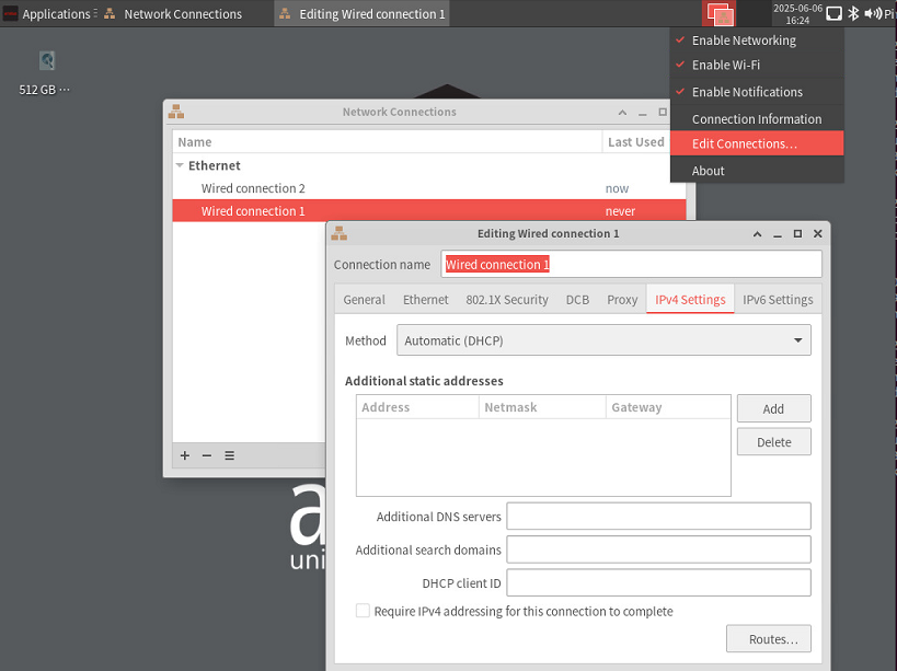
Network-Manager Applet GUI
For Desktop images, you can right-click the NetworkManager applet icon in the system tray and select the "Edit Connection" item to configure the network.
Connect to wireless network, you can left-click the NetworkManager applet icon in the system tray and select Available networks items to bring up a list of available wireless networks.
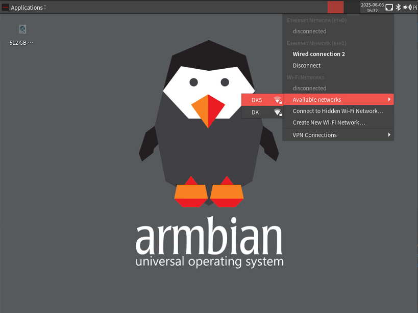
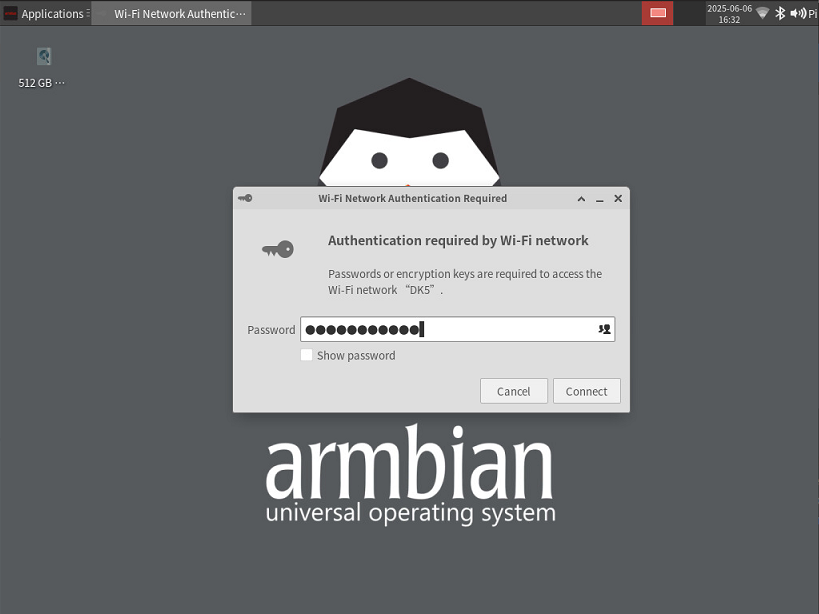
Click the network that you want to connect to. If the network is secured, a dialogue box will prompt you to enter the network key:
-
Netplan
The Desktop and CLI images come with a default Netplan YAML file located at etc/netplan/00-default-use-network-manager.yaml. These images use the NetworkManager backend by default. All Ethernet interfaces are configured for DHCP and will automatically obtain an IP address from your router.
# Added by Armbian # # Reference: https://netplan.readthedocs.io/en/stable/netplan-yaml/ # # Let NetworkManager manage all devices on this system. # Any device will come up with DHCP, once carrier is detected. # This is basically Netplan passing control over to NetworkManager at boot time. network: version: 2 renderer: NetworkManagerIf a Wi-Fi connection is successfully established during the first boot, a Wi-Fi Netplan YAML file will be created at /etc/netplan/30-wifis-dhcp.yaml. If no Wi-Fi connection is made during the first boot, this file can also be created manually after booting.
# Created by Armbian firstlogin script network: wifis: wlan0: dhcp4: yes dhcp6: yes access-points: "NETWORK": password: "password"More info of Netplan configuration, please refer to the Netplan docs
After YAML file changed, you should apply the configuration
$ sudo chmod 600 /etc/netplan/xxx.yaml $ sudo netplan apply -
Command Line configure wireless connection
-
check if your Wi-Fi radio is enabled:
$ nmcli radio wifiIf this command returns the text "enabled", you’re ready to configure a connection. If this command returns "disabled", try enabling Wi-Fi with the following command:
$ nmcli radio wifi on -
scan for wireless networks
$ nmcli dev wifi list IN-USE BSSID SSID MODE CHAN RATE SIGNAL BARS SECURIT> F8:8C:21:8E:D7:A3 DK Infra 1 540 Mbit/s 64 *** WPA1 WP> FA:8C:21:AE:D7:A3 -- Infra 1 540 Mbit/s 64 *** WPA1 WP> FA:8C:21:AE:D7:A5 -- Infra 149 540 Mbit/s 42 ** WPA1 WP> F8:8C:21:8E:D7:A5 DK5 Infra 149 540 Mbit/s 40 ** WPA1 WP>Look in the "SSID" column for the name of the network you would like to connect to. Use the SSID and a password to connect to the network.
-
Connect to a network
Run the following command to configure a network connection, replacing the <example_ssid> placeholder with the name of the network you’re trying to configure. Then enter your network password when prompted, the board should automatically connect to the network once you enter your password.
$ sudo nmcli --ask dev wifi connect <example_ssid> Password: ************** Device 'wlan0' successfully activated with '639d32e7-6516-44a5-a538-f80ad7ebe177'. -
check if you’re connected to a network
$ nmcli dev wifi listYou should see output similar to the following:
$ nmcli dev wifi list
IN-USE  BSSID              SSID  MODE   CHAN  RATE        SIGNAL  BARS  SECURIT>
        FA:8C:21:AE:D7:A3  --    Infra  1     540 Mbit/s  67      ***   WPA1 WP>
        F8:8C:21:8E:D7:A3  DK    Infra  1     540 Mbit/s  64      ***   WPA1 WP>
*       F8:8C:21:8E:D7:A5  DK5   Infra  149   540 Mbit/s  39      **    WPA1 WP>
        FA:8C:21:AE:D7:A5  --    Infra  149   540 Mbit/s  39      **    WPA1 WP>
-
-
Alternatively, You can also use armbian-config to configure networking configuration on all Armbian images.
$ sudo armbian-config --cmd BNS001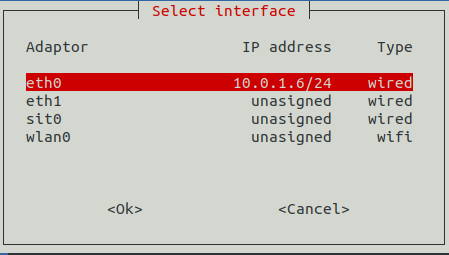
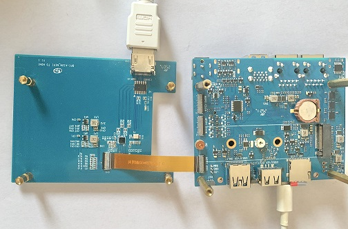
¶ Display
The RZ/V2N chip features a single MIPI DSI interface for display output. We have developed a DSI-to-HDMI adapter board and a 7-inch HC070 Touch Panel board.
-
HDMI
Connect the HDMI bridge board to the carrier board’s MIPI DSI interface using an FPC cable, It supports resolutions up to 1080p@60Hz.
-
Lcd Panel
Connect the Bananapi 7" HC070 touch panel to the carrier board’s MIPI DSI interface via an FPC cable. Enable panel-hc070iy30025 device-tree overlay.
overlays=panel-hc070iy30025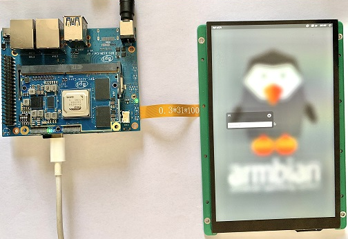
¶ RGB LED
The board has two RGB LEDs for user control
-
Yellow LED on carrier board, default state is heatbeat trigger
$ sudo sh -c 'echo timer > /sys/class/leds/carrier-led/trigger' -
Blue LED on core board, default state is default-on trigger
$ sudo sh -c 'echo none > /sys/class/leds/core-led/trigger'
¶ Fan
Control the fan’s on/off state via the hwmon sysfs interface.
-
Enable fan
$ sudo sh -c 'echo 1 > /sys/class/hwmon/hwmon3/fan1_target'-
Disable fan
$ sudo sh -c 'echo 0 > /sys/class/hwmon/hwmon3/fan1_target'¶ ADC
There have 3 units 12-bit adc in RZV2N, up to 8 channels per unit. The board adc pin header CN3 connected to adc1.
Read the adc data from iio sysfs
$ cat /sys/bus/iio/devices/iio:device1/in_voltage0_raw¶ M.2 NVME
The board has a PCIe ×2 m.2 M-key connector (Pcie 3.0), and standard M.2 2280 mounting hole, allowing for the deployment of an M.2 2280 NVMe SSD.
$ lspci
00:00.0 PCI bridge: Renesas Technology Corp. Device 1135
01:00.0 Non-Volatile memory controller: Kingston Technology Company, Inc. KC3000/FURY Renegade NVMe SSD [E18] (rev 01)You can verify the performance of your SSD on Pi Benchmarks using the following command:
$ wget https://raw.githubusercontent.com/TheRemote/PiBenchmarks/master/Storage.sh
$ chmod +x Storage.sh
$ sudo ./Storage.sh /path/to/storageTest results for sd, emmc and nvme ssd (KINGSTON SKC3000S512G)
Category |
Test |
Sdcard Test Result |
Emmc Test Result |
Nvme SSD Test Result |
HDParm |
Disk Read |
12.20 MB/s |
47.37 MB/s |
760.69 MB/s |
HDParm |
Cached Disk Read |
12.49 MB/s |
41.18 MB/s |
730.07 MB/s |
DD |
Disk Write |
14.4 MB/s |
66.6 MB/s |
162 MB/s |
FIO |
4k random read |
2328 IOPS (9313 KB/s) |
6623 IOPS (26494 KB/s) |
54759 IOPS (219037 KB/s) |
FIO |
4k random write |
944 IOPS (3777 KB/s) |
6450 IOPS (25801 KB/s) |
25793 IOPS (103173 KB/s) |
IOZone |
4k read |
11684 KB/s |
20569 KB/s |
94365 KB/s |
IOZone |
4k write |
4969 KB/s |
19340 KB/s |
60732 KB/s |
IOZone |
4k random read |
8902 KB/s |
20556 KB/s |
40856 KB/s |
IOZone |
4k random write |
5135 KB/s |
23332 KB/s |
107290 KB/s |
Score: 1371 |
Score: 5146 |
Score: 20342 |
¶ WIFI
Onboard wifi module is realtek rtl8821cu, IEEE 802.11b/g/n/ac(1T1R) USB2.0 WLAN and BT Module
$ ifconfig  wlan0
wlan0: flags=4163<UP,BROADCAST,RUNNING,MULTICAST>  mtu 1500
        inet 10.0.1.12  netmask 255.255.255.0  broadcast 10.0.1.255
        inet6 fe80::44a5:d624:e8e0:2bea  prefixlen 64  scopeid 0x20<link>
        ether 14:5d:34:49:97:8e  txqueuelen 1000  (Ethernet)
        RX packets 4343  bytes 838419 (818.7 KiB)
        RX errors 0  dropped 0  overruns 0  frame 0
        TX packets 507  bytes 41012 (40.0 KiB)
TX errors 0 dropped 0 overruns 0 carrier 0 collisions 0For detailed Wi-Fi configuration, please refer to the Networking section.
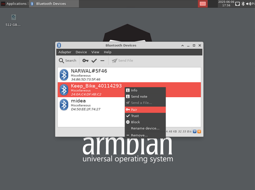
¶ Bluetooth
Onboard Bluetooth module is realtek rtl8821cu, IEEE 802.11b/g/n/ac(1T1R) USB2.0 WLAN and BT Module. The BT controller supports BT 4.2 system and compatibles Bluetooth 2.1+EDR.
$ hcitool dev
Devices:
hci0 14:5D:34:49:97:8FBluetooth adapters can be managed by blueman-manager or the bluetoothctl CLI tool.
-
Bluetooth using on Desktop image with Blueman
Right-click the bluetooth icon in the system tray and select Device item to the Bluetooth Device window.
-
Bluetooth using with bluetoothctl command
Install Bluez
$ sudo apt install bluezStart bluetoothctl
$ bluetoothctl
[bluetooth]# list
Controller 14:5D:34:49:97:8F bpi-ai2n [default]
[bluetooth]# power on
Changing power on succeeded
[bluetooth]# agent on
Agent is already registered
[bluetooth]# default-agent
Default agent request successful
[bluetooth]# discoverable on
Changing discoverable on succeeded
[CHG] Controller 14:5D:34:49:97:8F Discoverable: yes
[bluetooth]# pairable on
Changing pairable on succeeded
[bluetooth]# scan on
Discovery started
[CHG] Controller 14:5D:34:49:97:8F Discovering: yes
[NEW] Device 77:2B:0B:D7:28:A5 77-2B-0B-D7-28-A5
[NEW] Device 42:66:40:6D:8B:6F 42-66-40-6D-8B-6F
[NEW] Device 24:0A:C4:DF:4B:C2 Keep_Bike_40114293
[NEW] Device 34:86:5D:73:5F:46 NARWAL#5F46
[CHG] Device 24:0A:C4:DF:4B:C2 ServiceData Key: 00001818-0000-1000-8000-00805f9b34fb
[bluetooth]# pair TargetDeviceMac
¶ Camera
¶ Type-C OTG
The USB Type-c port Only support device mode.
¶ DTB overlay
DTB overlay is used for 40pin gpios multi-function configuration
pi@bpi-ai2n:/boot/dtb/renesas/overlay$ ls bpi-ai2n*
bpi-ai2n-i2c0-mux.dtbo               bpi-ai2n-spi0.dtbo
bpi-ai2n-i2c1.dtbo                   bpi-ai2n-spi2.dtbo
bpi-ai2n-i2c1-flash.dtbo             bpi-ai2n-spi2-flash.dtbo
bpi-ai2n-i2c1-rtc.dtbo               bpi-ai2n-spi2-waveshare-st7789v.dtbo
bpi-ai2n-i2c2.dtbo                   bpi-ai2n-spi2-waveshare-tft24.dtbo
bpi-ai2n-i2s3-nxez-pcm512x.dtbo      bpi-ai2n-spi2-waveshare-tft35c.dtbo
bpi-ai2n-i2s3-waveshare-wm8960.dtbo  bpi-ai2n-uart0.dtbo
bpi-ai2n-pwm.dtbo                    bpi-ai2n-uart2.dtbo
bpi-ai2n-pwmfan.dtboConfigure overlays with GUI tool armbian-config.
$ sudo armbian-config --cmd DTO001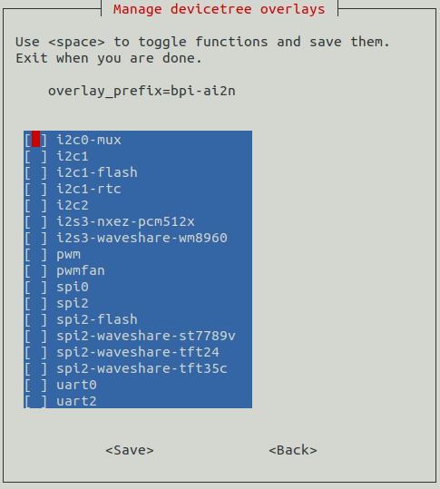
Alternatively, add names of overlays you want to activate to overlays= line in /boot/armbianEnv.txt, separated with spaces. For example, enable i2c2, spi2 and uart0 overlays
overlays=i2c1 spi2 uart0Reboot the board to apply overlays configuration
¶ Gpiod
Traditionally GPIO pins are exposed by Linux kernel under /sys/class/gpio namespace. However, this interface has been deprecated since version 4.8. The replacement is a C binding called libgpiod, along with a set of user land tools called gpiod.
-
Install Gpiod
$ sudo apt install gpiod -
List GPIO chips
print their labels and number of GPIO lines. Chips may be identified by number, name, or path. e.g. ‘0’, ‘gpiochip0’, and ‘/dev/gpiochip0’ all refer to the same chip.
$ sudo gpiodetect gpiochip0 [10410000.pinctrl] (96 lines) -
List GPIO lines
Print information about GPIO lines. Lines are specified by name, or optionally by offset if the chip option is provided. Each line corresponds to a GPIO pin, and the GPIO number of each pin is the line number plus 416.
$ sudo gpioinfo gpiochip0 - 96 lines: line 0: "P00" "carrier-led" output active-high [used] line 1: "P01" "core-led" output active-high [used] line 2: "P02" unused input active-high line 3: "P03" "interrupt" input active-high [used] ... line 93: "PB5" unused input active-high line 94: "PB6" unused input active-high line 95: "PB7" unused input active-high -
Get gpio line number from name, For example, 40pin header phy pin.31 name is P9_5.
$ sudo gpiofind P9_5 77 -
Read value of 40pin header phy pin.31
$ sudo gpioget gpiochip0 77 1 -
Set value of 40pin header phy pin.31 to low
$ sudo gpioset gpiochip0 77=0 -
Monitor GPIO level change event, You need to specify either -r for rising edge events or -f for falling edge events, but not both.
$ sudo gpiomon -r gpiochip0 77
event:  RISING EDGE offset: 77 timestamp: [   22813.801682561]
¶ Python3-gpiod
python3-gpiod is the Python binding for the libgpiod library, which allows users to control GPIO lines using Python,
-
Install python3-libgpiod
$ sudo apt install python3-libgpiod -
The following example code reads the state of the pin connected to 40pin physical pin.31.
import gpiod # 40pin, phy pin.31 LINE_OFFSET = 77 chip = gpiod.Chip("0", gpiod.Chip.OPEN_BY_NUMBER) line = chip.get_line(LINE_OFFSET) line.request(consumer='gpio', type=gpiod.LINE_REQ_DIR_IN) value = line.get_value() print(f"GPIO value is {value}") -
The following example code controls an LED connected to 40pin physical pin.31.
import time import gpiod # 40pin, phy pin.31 LINE_OFFSET = 77 chip = gpiod.Chip("0", gpiod.Chip.OPEN_BY_NUMBER) line = chip.get_line(LINE_OFFSET) line.request(consumer="gpio", type=gpiod.LINE_REQ_DIR_OUT, default_vals=[0]) try: while True: line.set_value(1) time.sleep(0.5) line.set_value(0) time.sleep(0.5) finally: line.set_value(1) line.release() -
The following example code reads the state of a button connected to 40pin physical pin.3, and lights an LED connected to physical 40pin pin.31 when the button is pressed:
import gpiod

# 40pin, phy pin.31
LED_LINE_OFFSET = 77

# 40pin, phy pin.3
BUTTON_LINE_OFFSET = 26

chip_led = gpiod.Chip("0", gpiod.Chip.OPEN_BY_NUMBER)
chip_button = gpiod.Chip("0", gpiod.Chip.OPEN_BY_NUMBER)

line_led = chip_led.get_line(LED_LINE_OFFSET)
line_led.request(consumer="LED", type=gpiod.LINE_REQ_DIR_OUT, default_vals=[0])

line_button = chip_button.get_line(BUTTON_LINE_OFFSET)
line_button.request(consumer="BUTTON", type=gpiod.LINE_REQ_DIR_IN)

try:
    while True:
        line_led.set_value(line_button.get_value())
finally:
    line_led.set_value(1)
    line_led.release()
    line_button.release()
¶ Python3-periphery
python-periphery is a pure Python library for GPIO, LED, PWM, SPI, I2C, MMIO, and Serial peripheral I/O interface access in userspace Linux.
dtb overlay must be enabled before using 40pin header bus control,
-
Install python3-periphery
$ sudo apt install python3-periphery -
The following example code reads the state of the pin connected to 40pin physical pin.31.
from periphery import GPIO # 40pin, phy pin.31 CHIP = "/dev/gpiochip0" LINE_OFFSET = 77 gpio = GPIO(CHIP, LINE_OFFSET, "out") gpio.write(True) print("GPIO state:", gpio.read()) gpio.close() -
The following example code controls an LED connected to 40pin physical pin.31.
import time from periphery import GPIO # 40pin, phy pin.31 CHIP = "/dev/gpiochip0" LINE_OFFSET = 77 gpio = GPIO(CHIP, LINE_OFFSET, "out") gpio.write(False) try: while True: gpio.write(True) time.sleep(0.5) gpio.write(False) time.sleep(0.5) finally: gpio.write(False) gpio.close() -
The following example code reads the state of a button connected to 40pin physical pin.3, and lights an LED connected to 40pin physical pin.31 when the button is pressed:
from periphery import GPIO # 40pin, phy pin.31 LED_CHIP = "/dev/gpiochip0" LED_LINE_OFFSET = 77 # 40pin, phy pin.3 BUTTON_CHIP = "/dev/gpiochip0" BUTTON_LINE_OFFSET = 26 led = GPIO(LED_CHIP, LED_LINE_OFFSET, "out") button = GPIO(BUTTON_CHIP, BUTTON_LINE_OFFSET, "in") try: while True: print(button.read()) led.write(button.read()) finally: led.write(True) led.close() button.close() -
The following example code reads the value of register 0x00 from a device with address 0x50, connected to I2C1 on the 40-pin physical pin.3 and pin.5. You need to enable the i2c1 DTB overlay first.
from periphery import I2C I2C_DEV = "/dev/i2c-1" SLAVE_ADDR = 0x50 i2c = I2C(I2C_DEV) msg = [I2C.Message([0x10]), I2C.Message([0x00], read=True)] i2c.transfer(SLAVE_ADDR, msg) print("I2C data read: 0x{:02x}".format(msg[1].data[0])) i2c.close() -
The following example code performs an SPI loopback test. Please directly connect 40-pin physical pin 19 (SPI2_MOSI) to physical pin 21 (SPI2_MISO). You need to load spidev driver module and enable the spi2 DTB overlay before the test.
from periphery import SPI SPI_DEV = "/dev/spidev2.0" data_out = [0xAA, 0xBB, 0xCC, 0xDD] try: spi = SPI(SPI_DEV, 0, 1000000) data_in = spi.transfer(data_out) print("Send Data: [0x{:02x}, 0x{:02x}, 0x{:02x}, 0x{:02x}]".format(*data_out)) print("Receive Data: [0x{:02x}, 0x{:02x}, 0x{:02x}, 0x{:02x}]".format(*data_in)) finally: spi.close() -
The following example code sends data via UART to a device connected to 40-pin physical pin 8 (UART2_TXD) and pin 10 (UART2_RXD). You need to enable the uart2 DTB overlay before the test.
from periphery import Serial

UART_DEV = "/dev/ttySC2"
BAUDRATE = 115200

serial = Serial(UART_DEV, BAUDRATE)
serial.write(b"Hello, World!\n")

serial.close()
¶ Adafruit-Blinka
Adafruit Blinka is a compatibility layer that brings the CircuitPython hardware API on Linux OS using Python3, making it easy to use sensors, displays, and other I2C/SPI/UART devices. More info please ref to Adafruit wiki and adafruit github
It already supports the RZ/V2N chip and the BPI-AI2N board. Dtb overlay must be enabled before using 40pin header bus control
-
Install packages
$ sudo apt install git gpiod python3-dev python3-libgpiod python3-periphery python3-pip python3-venv libjpeg-dev zlib1g-dev libfreetype-dev libfreetype6 fonts-dejavu -
Create a project and install a virtual python environment in it.
$ sudo su # mkdir project # cd project # python3 -m venv myenv # source myenv/bin/activate (myenv) root@bpi-ai2n:~/project# -
Install gpiod python binding library
(myenv) root@bpi-ai2n:~/project# pip3 install gpiod -
Virtual env Install Adafruit Blinka
-
Install from PyPI.
(myenv) root@bpi-ai2n:~/project# pip3 install Adafruit-Blinka -
Install from git source
(myenv) root@bpi-ai2n:~/project# pip3 install git+https://github.com/adafruit/Adafruit_Blinka
-
-
Blinka Test
-
The example test_blinka.py tests whether the Adafruit-Blinka package is installed correctly. Before running the test, please load spidev driver module, enable the i2c1 and spi2 DTB overlays.
import board import digitalio import busio print("Hello, blinka!") # pin.31, Try to create a Digital input pin = digitalio.DigitalInOut(board.D31) print("Digital IO ok!") # Try to create an I2C device i2c = busio.I2C(board.SCL, board.SDA) print("I2C ok!") # Try to create an SPI device spi = busio.SPI(board.SCLK, board.MOSI, board.MISO) print("SPI ok!") print("done!")The execution result of this example is as follows:
(myenv) root@bpi-ai2n:~/project# python3 test_blinka.py Hello, blinka! Digital IO ok! I2C ok! SPI ok! done! -
The following example code controls an LED connected to 40pin physical pin.31.
import time import board import digitalio print("hello blinky!") # pin.31 led = digitalio.DigitalInOut(board.D31) led.direction = digitalio.Direction.OUTPUT while True: led.value = True time.sleep(0.5) led.value = False time.sleep(0.5) -
The following example code reads the state of a button connected to 40pin physical pin.3, and lights an LED connected to 40pin physical pin.31 when the button is pressed:
import time import board import digitalio print("press the button!") # pin.31 led = digitalio.DigitalInOut(board.D31) led.direction = digitalio.Direction.OUTPUT # pin.3 button = digitalio.DigitalInOut(board.D3) button.direction = digitalio.Direction.INPUT button.pull = digitalio.Pull.UP while True: led.value = not button.value -
I2C rgb lcd test for MCP23017 I2C Lcd1602 Module
Installing libraries from git repo, these two repo forked from Adafruit_CircuitPython_CharLCD and Adafruit_CircuitPython_MCP230xx, modified to match the hardware MCP23017 I2C Lcd1602 Module. Examples in these two repo also should be modified to match the hardware design
(myenv) root@bpi-ai2n:~/project# pip3 install git+https://github.com/Dangku/Adafruit_CircuitPython_CharLCD (myenv) root@bpi-ai2n:~/project# pip3 install git+https://github.com/Dangku/Adafruit_CircuitPython_MCP230xxRunning test example
(myenv) root@bpi-ai2n:~/project# wget https://raw.githubusercontent.com/Dangku/Adafruit_CircuitPython_CharLCD/main/examples/charlcd_i2c_rgb_simpletest.py
(myenv) root@bpi-ai2n:~/project# python3 charlcd_i2c_rgb_simpletest.py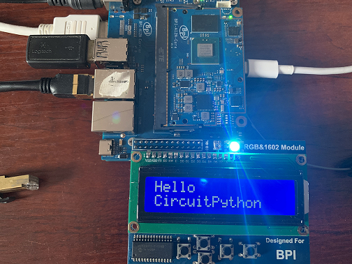
-
SPI oled test for SSD1306 SPI Oled Module
Installing the library from git repo, this repo forked from Adafruit_CircuitPython_SSD1306, libs and examples modified to match the hardware SSD1306 SPI Oled Module.
(myenv) root@bpi-ai2n:~/project# pip3 install git+https://github.com/Dangku/Adafruit_CircuitPython_SSD1306Installing pillow for some examples which import PIL, pip3 install Pillow command causes ImportError: cannot import name ‘_imagingft’ from ‘PIL’, so instead with the following command.
(myenv) root@bpi-ai2n:~/project# pip3 install Pillow --no-binary :all:Running test example
(myenv) root@bpi-ai2n:~/project# wget https://raw.githubusercontent.com/Dangku/Adafruit_CircuitPython_SSD1306/main/examples/ssd1306_stats.py
(myenv) root@bpi-ai2n:~/project# python3 ssd1306_stats.py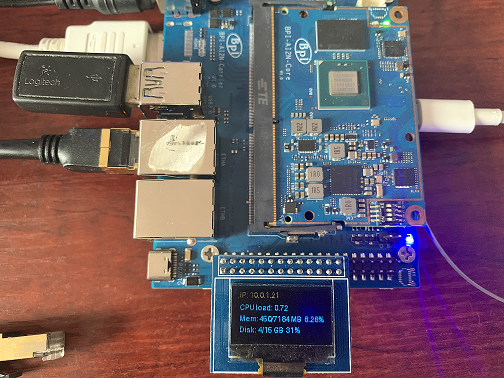
-
I2C oled test for SSD1306 I2C Oled Module
lib and examples source files are the same as spi ssd1306, but example must be modified to enable i2c interface and disable spi interface
# Create the I2C interface. i2c = board.I2C() # Create the SSD1306 OLED class. # The first two parameters are the pixel width and pixel height. Change these # to the right size for your display! disp = adafruit_ssd1306.SSD1306_I2C(WIDTH, HEIGHT, i2c) # Use for SPI #spi = board.SPI() # disp_cs = digitalio.DigitalInOut(board.CS) #disp_cs = None #disp_dc = digitalio.DigitalInOut(board.D18) #disp_reset = digitalio.DigitalInOut(board.D22) #disp = adafruit_ssd1306.SSD1306_SPI(WIDTH, HEIGHT, spi, disp_dc, disp_reset, dii sp_cs)Running test example
(myenv) root@bpi-ai2n:~/project# python3 ssd1306_stats.py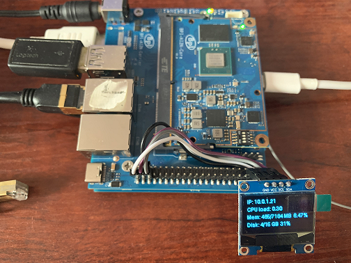
-
¶ WiringPi
Build and install wiringPi, for debian, you must install sudo before build
 $ sudo apt-get update
 $ sudo apt-get install build-essential git
 $ git clone https://github.com/Dangku/WiringPi
 $ cd WiringPi
 $ chmod a+x build
$ sudo ./buildRun gpio readall to show all 40pins status.
 $ sudo gpio readall
 +-----+-----+---------+------+---+-- AI2N --+---+------+---------+-----+-----+
 | I/O | wPi |   Name  | Mode | V | Physical | V | Mode |  Name   | wPi | I/O |
 +-----+-----+---------+------+---+----++----+---+------+---------+-----+-----+
 |     |     |    3.3V |      |   |  1 || 2  |   |      | 5V      |     |     |
 | 442 |   8 |   SDA.1 | HI-Z | 0 |  3 || 4  |   |      | 5V      |     |     |
 | 443 |   9 |   SCL.1 | HI-Z | 0 |  5 || 6  |   |      | 0V      |     |     |
 | 484 |   7 |  IO.484 | HI-Z | 0 |  7 || 8  | 0 | HI-Z | TxD2    | 15  | 460 |
 |     |     |      0V |      |   |  9 || 10 | 0 | HI-Z | RxD2    | 16  | 461 |
 | 488 |   0 |  IO.488 | HI-Z | 0 | 11 || 12 | 0 | HI-Z | IO.426  | 1   | 426 |
 | 489 |   2 |  IO.489 | HI-Z | 0 | 13 || 14 |   |      | 0V      |     |     |
 | 490 |   3 |  IO.490 | HI-Z | 0 | 15 || 16 | 0 | HI-Z | IO.463  | 4   | 463 |
 |     |     |    3.3V |      |   | 17 || 18 | 0 | HI-Z | IO.462  | 5   | 462 |
 | 508 |  12 |    MOSI | HI-Z | 0 | 19 || 20 |   |      | 0V      |     |     |
 | 507 |  13 |    MISO | HI-Z | 0 | 21 || 22 | 0 | HI-Z | IO.459  | 6   | 459 |
 | 509 |  14 |    SLCK | HI-Z | 0 | 23 || 24 | 0 | HI-Z | SS      | 10  | 503 |
 |     |     |      0V |      |   | 25 || 26 | 0 | HI-Z | IO.502  | 11  | 502 |
 | 432 |  30 |   SDA.2 | HI-Z | 0 | 27 || 28 | 0 | HI-Z | SCL.2   | 31  | 433 |
 | 491 |  21 |  IO.491 | HI-Z | 0 | 29 || 30 |   |      | 0V      |     |     |
 | 493 |  22 |  IO.493 | HI-Z | 0 | 31 || 32 | 0 | HI-Z | IO.456  | 26  | 456 |
 | 458 |  23 |  IO.458 | HI-Z | 0 | 33 || 34 |   |      | 0V      |     |     |
 | 427 |  24 |  IO.427 | HI-Z | 0 | 35 || 36 | 0 | HI-Z | IO.457  | 27  | 457 |
 | 495 |  25 |  IO.495 | HI-Z | 0 | 37 || 38 | 0 | HI-Z | IO.429  | 28  | 429 |
 |     |     |      0V |      |   | 39 || 40 | 0 | HI-Z | IO.420  | 29  | 420 |
 +-----+-----+---------+------+---+----++----+---+------+---------+-----+-----+
 | I/O | wPi |   Name  | Mode | V | Physical | V | Mode |  Name   | wPi | I/O |
+-----+-----+---------+------+---+-- AI2N --+---+------+---------+-----+-----+Set 40pin phy pin.31 high/low, wPi number is 22.
 $ sudo gpio mode 22 out
 $ sudo gpio write 22 1
$ sudo gpio write 22 0BPI GPIO Extend board and examples in WiringPi/examples
-
blinkall: blink leds connected to all gpio pins, no extend board.
-
lcd-adafruit: BPI LCD 1602 display module
-
oled: BPI OLED Display Module
-
ssd1306/oled: 0.96" I2C SSD1306 OLED
-
matrixled: BPI RGB LED Matrix Expansion Module
-
berryclip: BPI BerryClip Module
Note: This WiringPi only support set 40pin gpio to output, input, for io functions as i2c, spi, pwm…, you must enable dtb overlays
¶ RPi.GPIO
Build and install.
 $ sudo apt-get update
 $ sudo apt-get install build-essential python3 python3-pip python3-dev python3-setuptools git
 $ git clone https://github.com/Dangku/RPi.GPIO.git
 $ cd RPi.GPIO
 $ sudo python3 setup.py clean --all
$ sudo python3 setup.py installCreate and install wheel package
 $ sudo python3 setup.py bdist_wheel
$ sudo pip3 install dist/RPi.GPIO-XXX.whlInstall from git source directly without development
$ sudo pip3 install git+https://github.com/Dangku/RPi.GPIO.gitIf the package is already installed, it should be uninstalled before installing the new one, or installing the new one with --force-reinstall option.
-
The following example code controls an LED connected to 40pin physical pin.31.
import RPi.GPIO as GPIO
import time
import sys

# phy pin.31, bcm pin.6
bcmledpin = 6
phyledpin = 31

def setup_bcm():
  GPIO.setmode(GPIO.BCM)
  GPIO.setup(bcmledpin, GPIO.OUT)

def setup_board():
  GPIO.setmode(GPIO.BOARD)
  GPIO.setup(phyledpin, GPIO.OUT)

def blink_bcm():
  while True:
    GPIO.output(bcmledpin, GPIO.HIGH)
    print("********set bcm pin ", bcmledpin, " High********")
    time.sleep(1)
    GPIO.output(bcmledpin, GPIO.LOW)
    print("********set bcm pin ", bcmledpin, " Low********")
    time.sleep(1)

def blink_board():
  while True:
    GPIO.output(phyledpin, GPIO.HIGH)
    print("********set phy pin ", phyledpin, " High********")
    time.sleep(1)
    GPIO.output(phyledpin, GPIO.LOW)
    print("********set phy pin ", phyledpin, " Low********")
    time.sleep(1)

def shutdown():
    GPIO.cleanup()

if __name__ == '__main__':     # Program start
  print('To read output correctly, jumper pin 13 (bcm27) to pin 31 (bcm6)')
  print('Press Ctrl-C to exit')
  setup_bcm()
  #setup_board()
  print("Hardware information: ", GPIO.RPI_INFO)
  try:
    blink_bcm()
    #blink_board()
  except KeyboardInterrupt:
    shutdown()
¶ WiringPi-Python
Build and install.
 $ sudo apt-get update
 $ sudo apt-get install build-essential python3 python3-dev python3-setuptools swig git
 $ git clone --recursive  https://github.com/Dangku/WiringPi-Python.git
 $ cd WiringPi-Python
$ sudo python3 setup.py install-
The following example code controls an LED connected to 40pin physical pin.31.
#!/usr/bin/env python

import wiringpi as wpi
import time

# phy pin.31, wPi pin.22
PIN = 22

wpi.wiringPiSetup()
wpi.pinMode(PIN, 1)

while True:
    wpi.digitalWrite(PIN, 1)
    time.sleep(1)
    wpi.digitalWrite(PIN, 0)
    time.sleep(1)
¶ Install Docker Engine
Install Docker Engine with a simple command
$ curl -sSL get.docker.com | sudo shanother way install docker engine using armbian-config
$ armbian-config --cmd CON002Verify the Docker Engine is installed correctly by running the hello-world image.
 $ sudo docker run hello-world
 Unable to find image 'hello-world:latest' locally
 latest: Pulling from library/hello-world
 c9c5fd25a1bd: Pull complete
 Digest: sha256:0b6a027b5cf322f09f6706c754e086a232ec1ddba835c8a15c6cb74ef0d43c29
 Status: Downloaded newer image for hello-world:latest

 Hello from Docker!
 This message shows that your installation appears to be working correctly.

 To generate this message, Docker took the following steps:
  1. The Docker client contacted the Docker daemon.
  2. The Docker daemon pulled the "hello-world" image from the Docker Hub.
     (arm64v8)
  3. The Docker daemon created a new container from that image which runs the
     executable that produces the output you are currently reading.
  4. The Docker daemon streamed that output to the Docker client, which sent it
     to your terminal.

 To try something more ambitious, you can run an Ubuntu container with:
  $ docker run -it ubuntu bash

 Share images, automate workflows, and more with a free Docker ID:
  https://hub.docker.com/

 For more examples and ideas, visit:
https://docs.docker.com/get-started/¶ Remote access
Sometimes you need to access the board without connecting it to a monitor, keyboard, and mouse, To remotely control your bananapi board from another device on your local network, use one of the following services:
-
SSH
-
VNC
Before enabling remote access, please find the ip address of your board
-
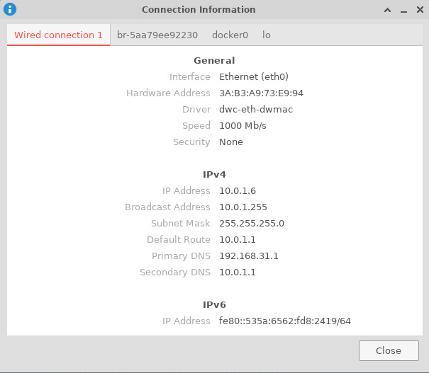
Desktop
Right click the nm applet icon in the system tray, and click Connection Information item, popup window displays all the network information.
-
Command line
Run the following command to output your IP address to the command line:
 $ hostname -I
10.0.1.6¶ SSH
Open a terminal window on your computer and enter the following command, replacing the <ip address> placeholder with the IP address of bananapi board you’re trying to connect to and <username> with your username:
$ ssh <username>@<ip address>¶ VNC
-
Install x11vnc
$ sudo apt install x11vnc -
Create a password file
$ x11vnc -storepasswd Enter VNC password: Verify password: Write password to /home/pi/.vnc/passwd? [y]/n y Password written to: /home/pi/.vnc/passwd -
Create service file /lib/systemd/system/x11-vnc.service
[Unit] Description="x11vnc" Requires=display-manager.service After=lightdm.service [Service] ExecStart=/usr/bin/x11vnc -auth guess -loop -forever -safer -shared -ultrafilexfer -bg -o /var/log/x11vnc.log ExecStop=/usr/bin/killall x11vnc [Install] WantedBy=multi-user.target -
Enable service
sudo systemctl daemon-reload sudo systemctl enable x11-vnc sudo systemctl start x11-vnc -
Connect to VNC server
Install tigervnc and launch it on the client device
 $ sudo apt install tigervnc-viewer
 $ vncviewer 10.0.1.6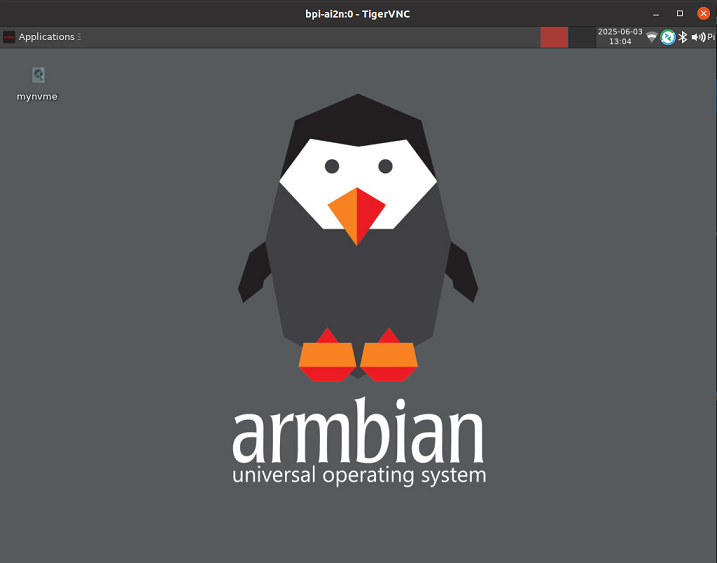
¶ System Localisation
Using armbian-config tool to change global timezone, language, keyboard layout and hostname
$ sudo armbian-config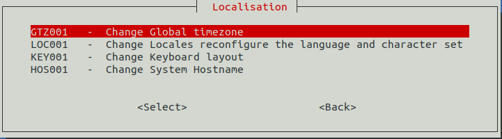
¶ Yocto AI SDK
¶ Prepare
-
Yocto image support SDcard or EMMC bootup.
-
It’s recommended to use A1 rated cards, 16GB at least.
-
Make sure bootable EMMC is formatted if you want bootup from SDcard Yocto
-
Download latest Yocto Image, and confirm that the checksum is correct.
-
root login without passwd.
¶ Install Yocto Image to SDcard
-
Install Image with Balena Etcher on Windows, Linux and MacOS.
Balena Etcher is an opensource GUI flash tool by Balena, Flash OS images to SDcard or USB drive.
-
Click on "Flash from file" to select image.
-
Click on "Select target" to select USB device.
-
Click on "Flash!" Start burning.
-
-
Install Image with Balena Cli on Windows, Linux and MacOS.
Balena CLI is a Command Line Interface for balenaCloud or openBalena. It can be used to flash linux image. Download the installer or standalone package from balena-io and install it correctly to your PC, then you can use the "local flash" command option of balena to flash a linux image to sdcard or usb drive.
$ sudo balena local flash core-image-weston-bananapi-ai2n-xxx.rootfs.wic.gz $ sudo balena local flash core-image-weston-bananapi-ai2n-xxx.rootfs.wic.gz --drive /dev/sdX $ sudo balena local flash core-image-weston-bananapi-ai2n-xxx.rootfs.wic.gz --drive /dev/sdX --yes -
Install Image with Armbian Imager on Windows, Linux and MacOS.
Armbian Imager is an open-source imaging tool for installing Armbian OS.
For un-official board images, please select Use Custom Image→Browse and select the local image file→Select the target storage→Erase&Flash.
-
Install Image with dd command on Linux
umount SDcard device /dev/sdX partition if mounted automatically.
 $ sudo apt-get install gunzip pv
 $ sudo sh -c 'gunzip -c core-image-weston-bananapi-ai2n-xxx.rootfs.wic.gz | pv | dd of=/dev/sdX bs=1M status=progress && sync'
¶ Install Yocto Image to eMMC
-
Prepare a SDcard with Linux image flashed and bootup board with this SDcard.
-
Copy Linux image to udisk, plug the udisk to board and mount it.
-
Install with dd command, umount mmcblk0p1 and mmcblk0p2 partition if mounted automatically.
 $ sudo apt-get install gunzip pv
 $ sudo sh -c 'gunzip -c core-image-weston-bananapi-ai2n-xxx.rootfs.wic.gz | pv | dd of=/dev/sdX bs=1M status=progress && sync'
¶ Build Yocoto AI SDK Source Code
¶ Yocto AI SDK and AI Application
¶ Other Development
¶ Flash Spi Bootloader
The SPI bootloader consists of three parts: the Flash Writer file, ATF firmware, and U-Boot. There are three files: Flash_Writer*.mot, bl2_bp_spi.srec(bl2_bp_spi.bin), and fip.srec(fip.bin), which can be found in the /boot directory of the Linux image.
-
Flash bootloader via the serial port
-
Copy Flash_Writer*.mot, bl2_bp_spi.srec and fip.srec to your Windows PC.
-
Connect Windows PC to Board via usb cabe to usb typec uart port bellow core board.
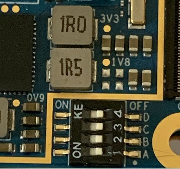
-
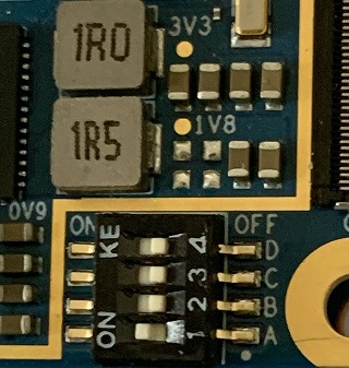
Change Bootsel Switch to SCIF download mode.
-
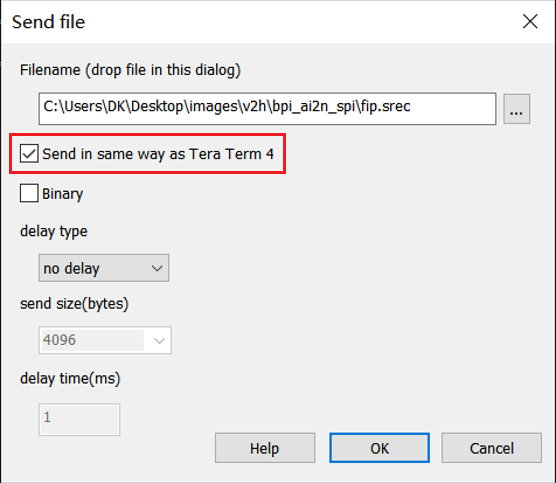
On Windows PC, open the terminal emulator. Here, we use Tera Term 4.108 as an example.
Note: Select "Send in same way as Tera Term 4" in Send file Window if Tera Term 5.x version used.
-
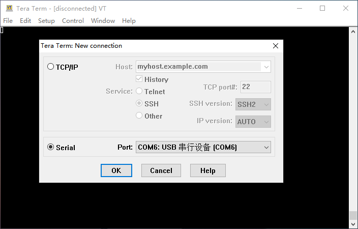
Select "File" > "New Connection" and select "Serial" port as shown below.
-
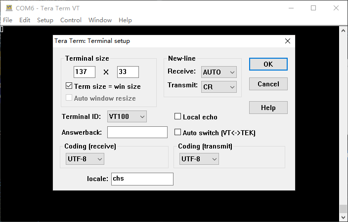
Open the configuration window from the "Setup">"Terminal" and change the setting as follows.
-
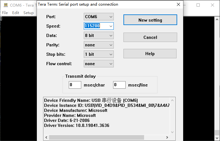
Open the configuration window from the "Setup">"Serial port" and change the setting as follows.
-
Connect the power cable to power on the board and following message will be displayed on the terminal.
SCI Download mode (Normal SCI boot) -- Load Program to SRAM --------------- -
Open "File" > "Send file…" and send the Flash Writer file (*.mot) as a text. If following message is displayed, the file transfer succeeded.
Flash writer for RZ/V2x Series Vx.xx xxx.xx,20xx Product Code : RZ/V2x > -
Enter "XLS2" on the terminal to get following messages.
> XLS2 ===== Qspi writing of RZ/V2x Board Command ============= Load Program to Spiflash Writes to any of SPI address. Program size & Qspi Save Address ===== Please Input Program Top Address ============ Please Input : H' -
Enter "8101e00". The log continues.
Please Input : H'8101e00 ===== Please Input Qspi Save Address === Please Input : H' -
Enter "00000". The log continues.
Please Input : H'00000 please send ! ('.' & CR stop load) -
After the "please send!" message, open "File" > "Send file…" and send the bl2_bp_spi-rzv2*.srec file as a text from the terminal software.
-
In case a message to prompt to clear data like below, please enter "y".
SPI Data Clear(H'FF) Check : H'00000000-0000FFFF,Clear OK?(y/n) -
Following log will be displayed. The end address is depending on the version of AI SDK.
Write to SPI Flash memory. ======= Qspi Save Information ================= SpiFlashMemory Stat Address : H'00000000 SpiFlashMemory End Address : H'00036D17 =========================================================== -
Enter "XLS2" on the terminal to get following messages.
> XLS2 ===== Qspi writing of RZ/V2x Board Command ============= Load Program to Spiflash Writes to any of SPI address. Program size & Qspi Save Address ===== Please Input Program Top Address ============ Please Input : H' -
Enter "00000". The log continues.
Please Input : H'00000 ===== Please Input Qspi Save Address === Please Input : H' -
Enter "60000". The log continues.
Please Input : H'60000 please send ! ('.' & CR stop load) -
After the "please send!" message, open "File" > "Send file…" and send the fip-rzv2*.srec file as a text from the terminal software.
-
In case a message to prompt to clear data like below, please enter "y".
SPI Data Clear(H'FF) Check : H'00000000-0000FFFF,Clear OK?(y/n) -
Following log will be displayed. The end address is depending on the version of AI SDK.
Write to SPI Flash memory. ======= Qspi Save Information ================= SpiFlashMemory Stat Address : H'00060000 SpiFlashMemory End Address : H'0011C2EE =========================================================== -
Power-off the board and change Bootsel Switch to default Boot Mode for booting the board.
-
¶ Erase emmc
Bootup the board with sdcard, erase the emmc with dd command as follows.
$ sudo dd if=/dev/zero of=/dev/mmcblk0 bs=1M status=noxfer
$ sync¶ Third part carrier board
-
Waveshare JETSON-IO-BASE-A carrier board
Edit /boot/armbianEnv.txt in armbian image or /boot/env.txt in yocto image as follow.
overlay_prefix=bpi-ai2n-waveshare-jetson-io fdtfile=renesas/bananapi-ai2n-waveshare-jetson-io-a.dtbNote:
-
HDMI and DP are not support by AI2N hardware.
-
JETSON-IO-BASE-A use 5V DC, not 12V.
-