¶ User Manual for BPI-VP10 Servo Module
¶ 1 Wiring Instructions
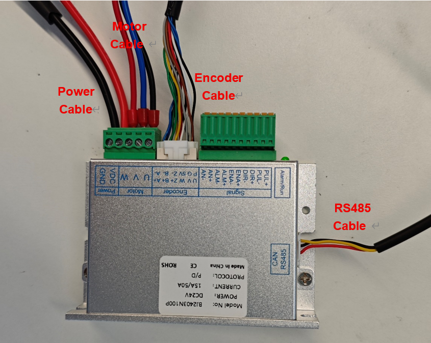
Connect the power, motor, encoder, and RS485 cables in the specified order. A 24V DC power supply is required. Important: Before applying main power, verify that the power cable polarity is correct to prevent damage.
¶ 2 Trial Run and Test
Please use the FortiorTechServoStudio PC software for commissioning and test running.
¶ 2.1 Communication Connection
(1) Install the serial driver.
(2) Connect the PC and the drive via the RS485 cable.
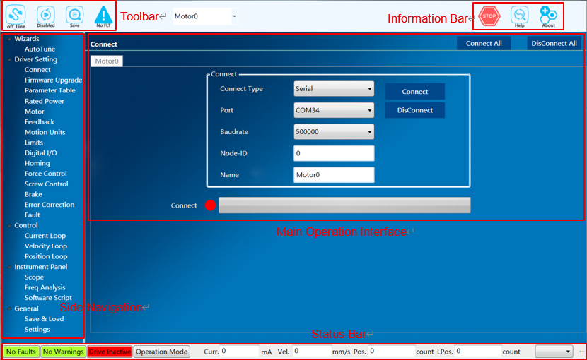
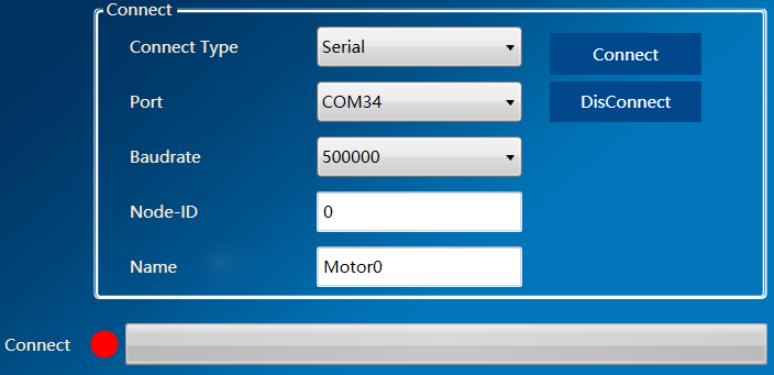
(3) Open FortiorTechServoStudio.exe and click the "Connect" submenu in the side navigation panel.
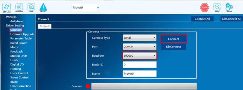
(4) Refresh the port list from the dropdown, select the port for the drive, and set the baud rate to 500000.
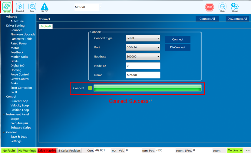
(5) Click "Connect" to establish the communication link.
¶ 2.2 Importing Parameters
When using the servo drive module for the first time, you can start by importing the parameters:
(1) In the side navigation bar, click the "Backup & Restore" submenu.
(2) Click "Load" select the .rpc file from the attachment, and wait a moment until the "Import parameters successfully" prompt box appears.
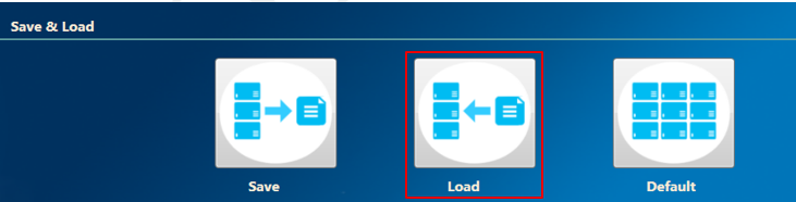
(3) On the top toolbar, click the "Save" button to save the parameters to the drive’s Flash memory.

¶ 2.3 Hall Learning
Since the matching motor encoder type is ABZ+Hall, a "Hall Learning" process is required during the initial adaptation.
Hall learning includes automatic commutation, which is used to determine the motor phase sequence, verify if the motor pole pairs or pole pitch match the set values, and determine the electrical angle offset. During automatic commutation, the motor will move a distance equal to one magnetic pole.
Hall learning determines the relationship between Hall signals and the motor’s electrical angle. During this process, the motor will move by one magnetic pole distance. After completing Hall learning, simply save the parameters to Flash or to a local parameter file. As long as the motor UVW wiring sequence is not modified, you only need to load parameters from Flash or import the parameter file in the future. The motor can run speed and position loops directly upon the next power-on without repeating the Hall learning process.
Hall Learning Steps:
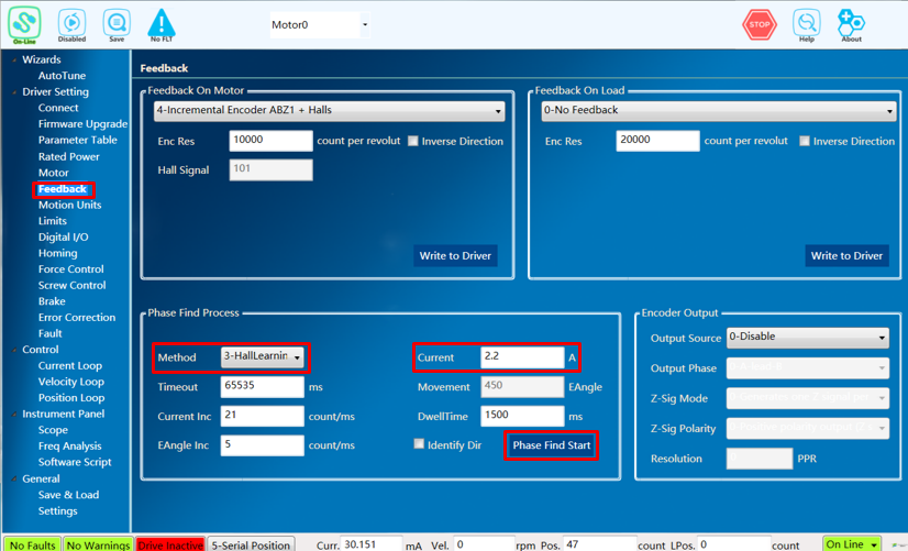
(1) In the side navigation bar, click the "Feedback" submenu.
(2) Set "Phasing Method" to "3-HallLearning" and set the Phasing Current to 2.2A.
(3) Click the "Phase Find Start" button.
(4) A prompt box will appear upon successful completion. If it fails, try increasing the phasing current, check that the motor and feedback parameters are set correctly, and ensure the motor readings and Hall signals are normal.
¶ 2.4 Running the Motor
Since the parameter file imported earlier already includes pre-tuned gains for the three loops, you can skip the tuning process and run the position loop directly.
Position Loop Steps:
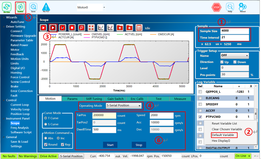
① Set the Oscilloscope "Sample Size" to 4000 and "Time Interval" to 21.
② Right-click on the oscilloscope recording variables and select "Default Variable".
③ Click the "Continuous Sampling" button in the oscilloscope to start waveform acquisition.
④ Set "Operation Mode" to "5-Serial Position".
⑤ Click the "Enable" button on the top toolbar to enable the position loop.
⑥ In "Motion Command", select "Incremental," "Round," and "Repeat". Set a suitable distance for "Target Position", set "Speed" to 40% of the rated speed, use a relatively low value for "Acceleration", set "Time" to 500ms, and click the "Start" button.
¶ 3 Updating the Firmware
¶ 1 Update Firmware via Fortior Emulator
To update the firmware, you must use Fortior’s development environment, FTM32ForgeIDE, via the Fortior emulator to download the new program.
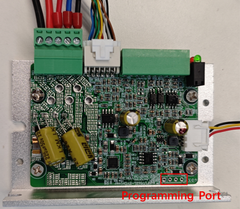
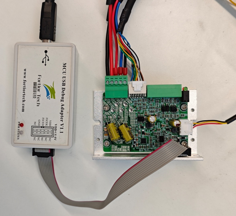
Please download the Fortior FTM32ForgeIDE from https://www.fortiortech.com/en/download/FTM32ForgeIDE and use the default settings during installation. Connect the Fortior emulator to the board’s download port. The pinout definition is as follows:
| Emulator | Board Programming Port |
|---|---|
VDD |
V |
FICEK |
K |
FICED |
D |
GND |
G |
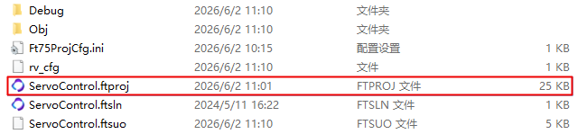
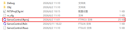
Double-click the .ftproj file to open the project
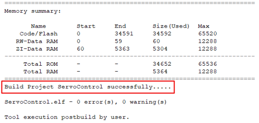
Once compiled successfully, the Output window will display "Build Project successfully."
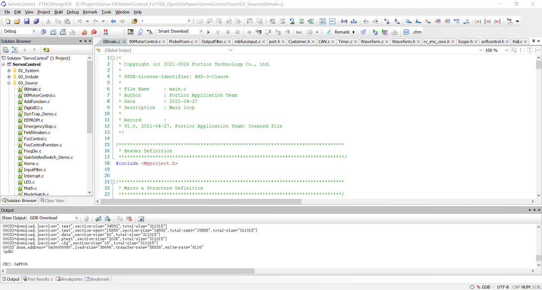
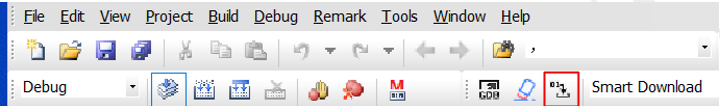
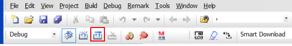
Click the button as following picture to download the program to the board.
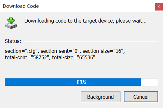
When the download progress bar reaches 100%, the code has been successfully downloaded to the chip.
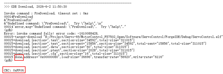
After a successful download, the Output window will display "done," and a non-zero CRC value indicates that the verification was successful.
¶ 2 Update Firmware via Serial Port
The board is pre-flashed with a Bootloader at the factory, allowing the program to be updated via the serial port. Double-click ServoControl_App.ftproj to open the project.
Click the button to compile the code.
Once compilation is complete, the Output window will display the information shown below. Please ignore the error message.
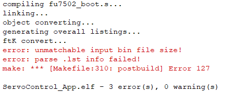
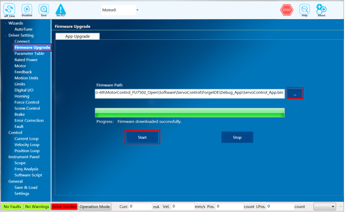
A new ServoControl_App.bin file will be generated in the ServoControl\ForgeIDE\Debug_App folder. Select the appropriate communication connection settings (you do not need to click "Connect").
Open the firmware download page, select the ServoControl_App.bin file just generated, and click "Start". When the progress bar reaches 100%, it indicates that the program has been successfully downloaded to the chip.
| 1.If the firmware download is interrupted or an anomaly prevents the board from connecting to the host computer, click "Start" first, then power on the board. 2.The board is shipped with a Bootloader. Please note that if you have used a Fortior emulator to download a program to the board, it will no longer be possible to update the program via the serial port. |