¶ Introduction
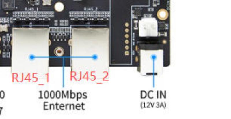
BananaPi BPI-F3 adopts K1 core, SPM8821 PMIC+external DCDC power supply scheme. Storage adopts LPDDR4X and eMMC. There are peripheral devices such as PCIe 2.0 2 lane M.2 KEY M, PCIe 2.0 1 lane MINI PCIe, 4xUSB3.0 TYPE-A, WIFI/BT, TF Card, HDMI TX, MIPI DSI, MIPI CSI, TYPE-C, 2xRJ45, etc. Integrated, integrating a stable and scalable solution.
| More Infomation: Banana Pi BPI-F3 Main Page |
¶ Development
¶ Prepare
-
Prepare a TTL cable, a 12V PD power supply, USB cable, and a minimum of 8G TF card.
-
Please download the SD and EMMC images to be burned.
-
Please note that the image ending with "bianbu-k1-xxx.img.zip" is the SD card image, while the image ending with "bianbu-k1-xxx.zip" is the EMMC image. Please do not make the wrong selection when burning.
¶ Install Image to SDcard
| Please select the image ending in "bianbu-k1-xxx.img.zip" for Bianbu. Don’t choose the wrong one! |
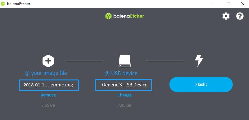
Balena Etcher is an opensource GUI flash tool by Balena, Flash OS images to SDcard or USB drive.
-
Click on "Flash from file" to select image.
-
Click on "Select target" to select USB device.
-
Click on "Flash!" Start burning.
| Remember to connect to the HDMI screen when starting, and then create your own account. |
¶ Install Image to eMMC 1
| Please select the image ending in "bianbu-k1-xxx.zip" for Bianbu. Don’t choose the wrong one! |
Install driver software
-
Double click titantools_for_windows-latest to install. Linux grants executable permissions and can be run by opening titantools_for_Linux-latest without the need for installation.
-
It is installed on the computer’s C drive by default, and will require a certain amount of space for future use. So please ensure that the remaining available space is greater than 10G (Linux has a Home space greater than 10GB)
-
Allow this app from unknown publishers to make changes to your device. Then choose to always install this driver software.
-
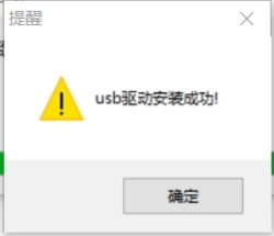
If the driver installation is successful, it will prompt that the USB driver installation is successful.
Visual software burns img to eMMC
-
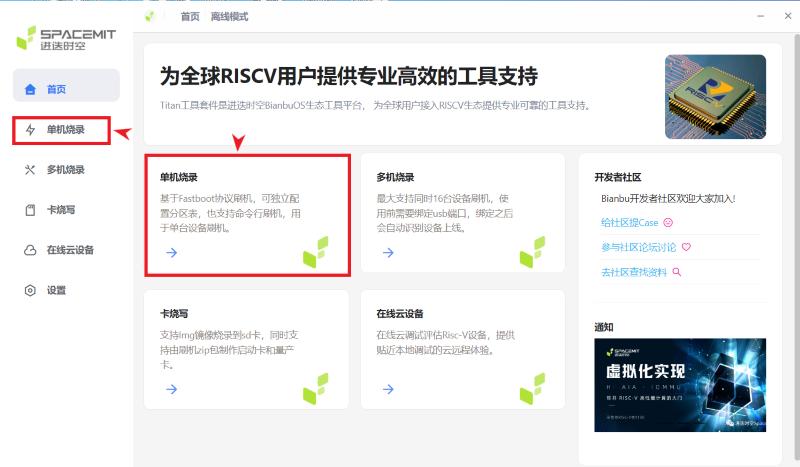
Click Single Machine Burn (If you need to burn multiple devices simultaneously, click Multiple Machine Burn)
-
To put the device into flashing mode:
-
Method 1:
The device is not powered on. Press and hold the DOWNLOAAO (FDL) button, plug in the type-c, and then release the button. (If you are worried about insufficient USB power, you can first plug in the power, then release the button, and then plug in the USB cable) -
Method 2:
The device is powered on. Press and hold the DOWNLOAD (FDL) button, then press the Reset button, and then plug in the USB cable.When connected to a USB HUB, there may be a "Fastboot device initialization failure". 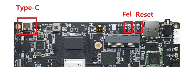
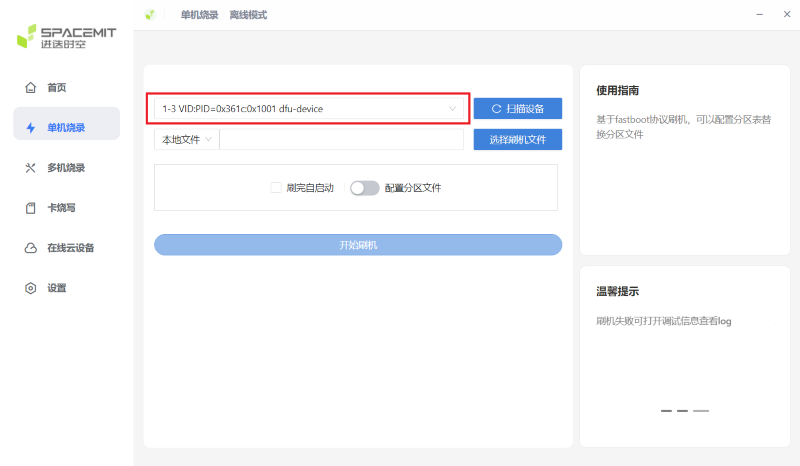
If the software recognition is successful, a "VID:PID=" display will appear. If there are multiple devices, please select the device you want to burn.
-
-
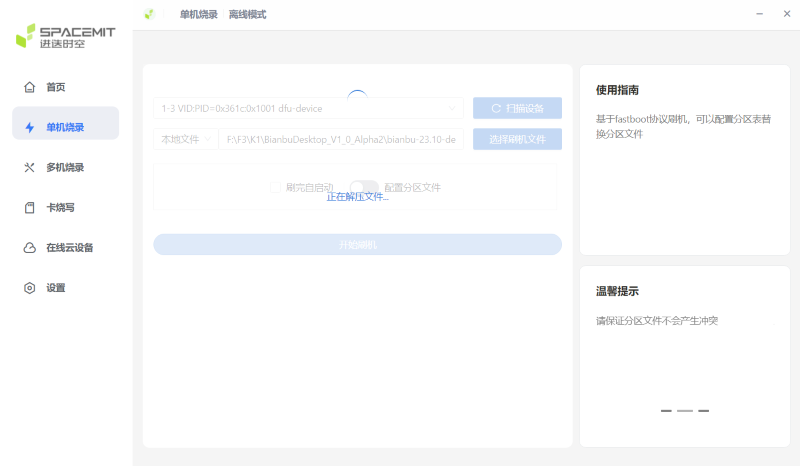
Select the flash file, the software will decompress it, please be patient and wait for a while.
-
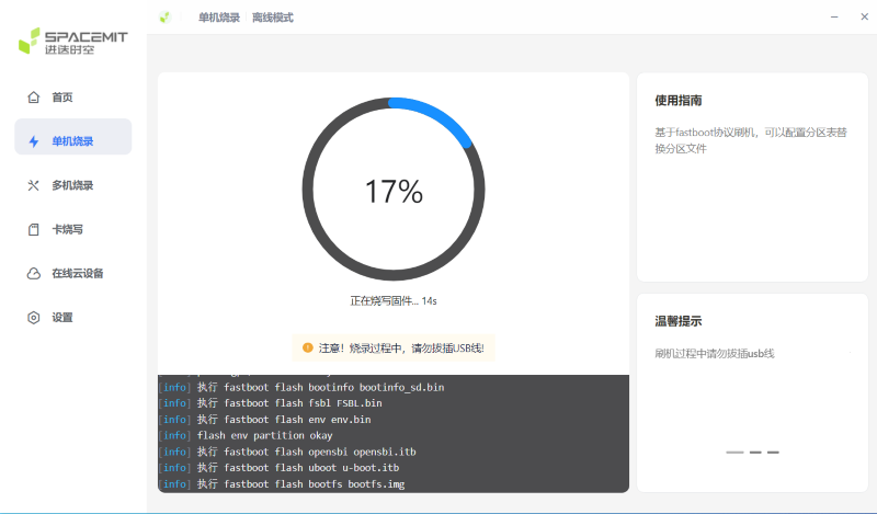
Click to start flashing.
-
Burn completed, power on again.
Non-visual software burns image to eMMC
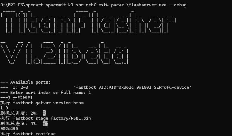
This is another way of burning.Use the titanflasher tool,then put this flashserver.exe file under the EMMC image file you want to burn.
Run it on your computer as shown in the following screenshot:
When the system recognizes the device(VID:=PID=XXX), select "1" item to brush the machine.
¶ Install Image to eMMC 2
| The Armbian image currently only supports SD card startup. |
| In addition to using titantools, you can also use the dd command to burn the image to emmc. |
Take bianbu-23.10-nas-k1-v1.0rc1-release-20240429192450.img. Unzip the "bianbu-k1-xxx.img.zip" to the USB drive, and then copy the "fsbl.bin" and "bootinfo_emmc.bin" in "bianbu-k1-xxx.zip" to copy it into the USB drive.
-
Firstly, insert the SD card that has been burned into the image into F3 and power it on to start.
-
Insert the copied USB drive into F3.
-
After startup, use the "lsblk" command to view.
pi@k1:~$ lsblk NAME MAJ:MIN RM SIZE RO TYPE MOUNTPOINTS sda 8:0 1 14.8G 0 disk └─sda1 8:1 1 14.8G 0 part mmcblk0 179:8 0 14.8G 0 disk ├─mmcblk0p1 179:9 0 256K 0 part ├─mmcblk0p2 179:10 0 128K 0 part ├─mmcblk0p3 179:11 0 384K 0 part ├─mmcblk0p4 179:12 0 2M 0 part ├─mmcblk0p5 179:13 0 256M 0 part └─mmcblk0p6 179:14 0 8G 0 part / mmcblk2 179:8 0 14.6G 0 disk"sda1" refers to a USB drive, "mmcblk0" refers to an SD card, and "mmcblk2" refers to an EMMC.
-
Mount the USB drive to mnt first.
sudo mount /dev/sda1 /mnt cd /mnt -
Then use the dd command to burn the image to emmc
sudo dd if=bianbu-23.10-nas-k1-v1.0rc1-release-20240429192450.img of=/dev/mmcblk2 bs=10MIf you enter the lsblk command, you can see BOOT. You can go directly to step 9. -
Next, update the boot0 partition of EMMC. However, some image boot partitions are hidden by default, so you need to modify the cmdline. Mount bootfs:
sudo mount /dev/mmcblk0p5 /boot sudo nano /boot/env_k1-x.txtFind Commonargs and add "recovery=1" at the end.
commonargs=setenv bootargs earlycon=${earlycon} earlyprintk console=tty1 console=${console} ${loglevel} clk_ignore_unused rdinit=${init} recovery=1Save and restart.
sudo reboot -
After the restart is completed, you can see the BOOT partition using the lsblk command.
pi@k1:~$ lsblk NAME MAJ:MIN RM SIZE RO TYPE MOUNTPOINTS sda 8:0 1 14.8G 0 disk └─sda1 8:1 1 14.8G 0 part mmcblk0 179:0 0 14.8G 0 disk ├─mmcblk0p1 179:1 0 256K 0 part ├─mmcblk0p2 179:2 0 128K 0 part ├─mmcblk0p3 179:3 0 384K 0 part ├─mmcblk0p4 179:4 0 2M 0 part ├─mmcblk0p5 179:5 0 256M 0 part └─mmcblk0p6 179:6 0 8G 0 part / mmcblk2 179:8 0 14.6G 0 disk ├─mmcblk2p1 179:9 0 256K 0 part ├─mmcblk2p2 179:10 0 64K 0 part ├─mmcblk2p3 179:11 0 1M 0 part ├─mmcblk2p4 179:12 0 2M 0 part ├─mmcblk2p5 179:13 0 256M 0 part └─mmcblk2p6 179:14 0 2G 0 part mmcblk2boot0 179:16 0 4M 1 disk mmcblk2boot1 179:24 0 4M 1 disk -
Mount a USB drive
sudo mount /dev/sda1 /mnt cd /mnt -
Execute the following command:
echo 0 | sudo tee /sys/block/mmcblk2boot0/force_ro sudo dd if=bootinfo_emmc.bin of=/dev/mmcblk2boot0 sudo dd if=FSBL.bin of=/dev/mmcblk2boot0 seek=512 bs=1 sync -
After waiting for the burning to complete, disconnect the power and remove the SD card and USB drive. Power on again to start from the EMMC.
¶ Solution for 2G DDR version unable to start
| There are currently issues with the linux-1.0.35_beta version. Please use the Windows version of the tool first. |
-
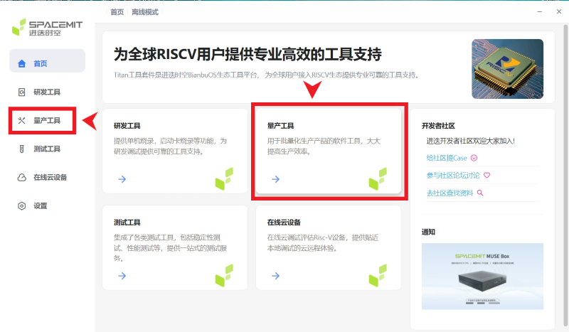
Open Titan Tools and click on the mass production tool.
-
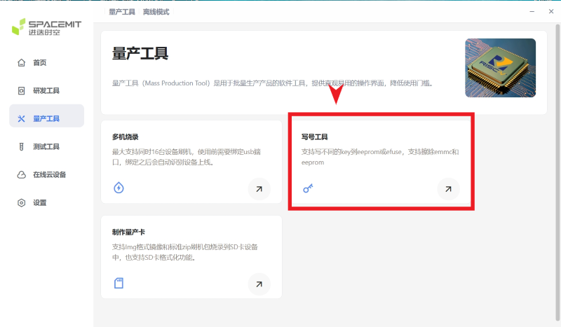
Select the number writing tool. If your software does not have this, please update it.
-
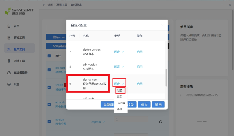
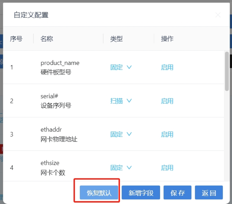
Select Configure custom fields and change ddr_cs_num from fixed to scan. Click Save and then return.
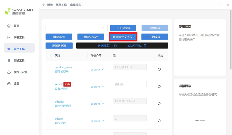
(If you do not see the ddr_cs_num option, please click Restore Default first)
-
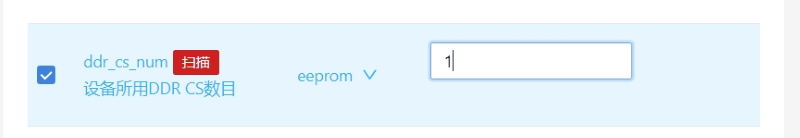
Select ddr_cs_num. Change 2 to 1.
-
While holding down the FDL button, connect the type-c cable to the board. After the board is recognized, click Start writing.
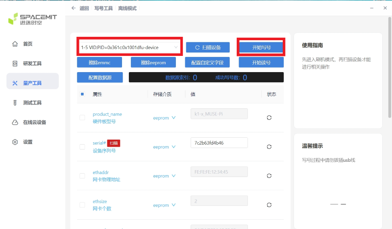
After clicking "Start writing number", you may be asked to enter again. Re-enter 1 and press Enter. Wait for the number to be written successfully.
¶ Other Development
¶ Network
¶ WiFi/BT
You have two ways to setup WiFi
-
Use UI interface to setup WiFi
-
Use commands to setup WiFi
sudo nmcli dev
sudo nmcli r wifi on
sudo nmcli dev wifi
sudo nmcli dev wifi connect "SSID" password "PASSWORD" ifname wlan0
You have two ways to setup BT
-
Use UI interface to setup BT
-
Use commands to setup BT
hciconfig
sudo hciconfig hci0 up
hciconfig hci0 noauth
hcitool scan
sudo rfcomm bind /dev/rfcomm0 xx:xx:xx:xx
sudo cat >/dev/rfcomm0
¶ Storage
¶ KEY.M
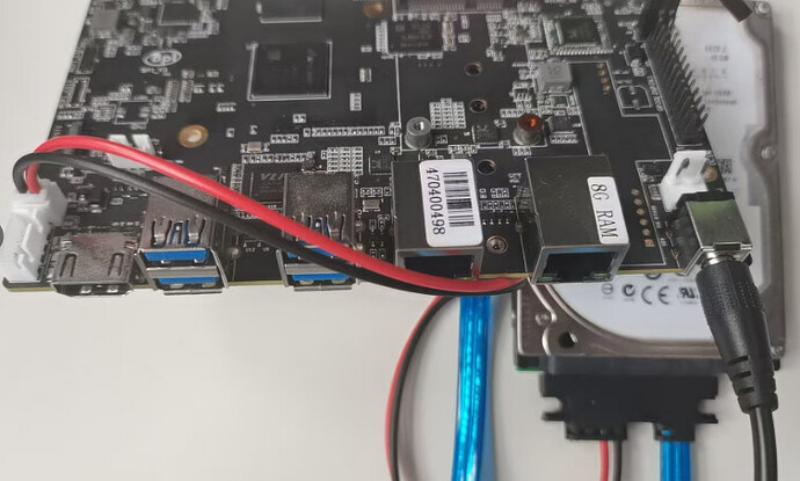
This interface allows you to connect SSDs that comply with the NMVe protocol, or you can use other compatible KEY.M adapter boards.
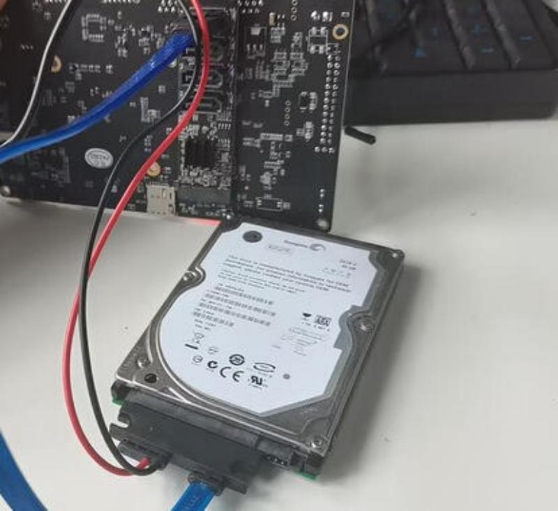
Take the conversion from KEY.M to STAT as an example
-
Connect the equipment to the BPI-F3 board.
-
Query the storage of the corresponding device
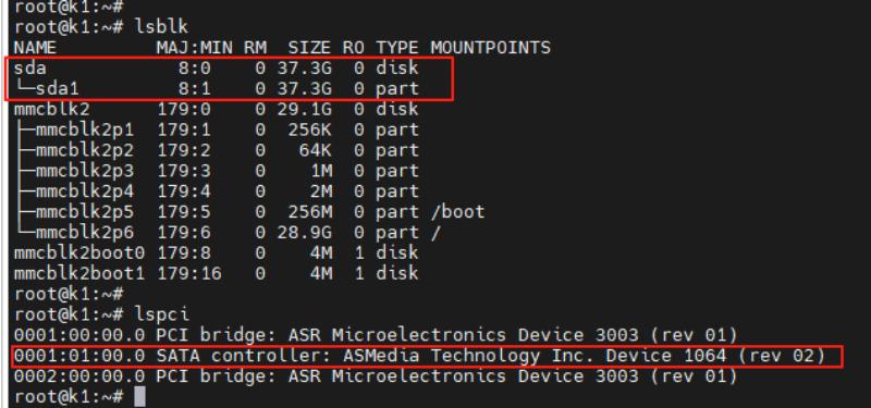
-
Now it has been identified and this device can be used.
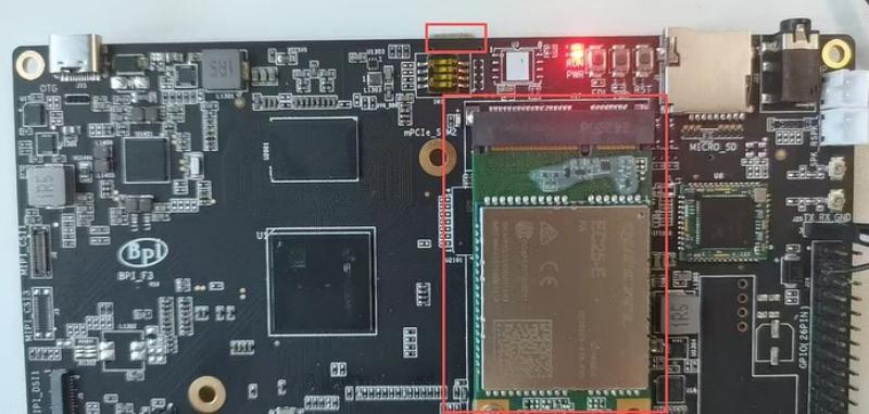
¶ mPCIe
Here we take the EC25-E module as an example.
-
Insert the SIM card and the EC25-E module onto the BPI-F3, and then power it on to start.
-
Use the instruction query module to check the status.
lsusb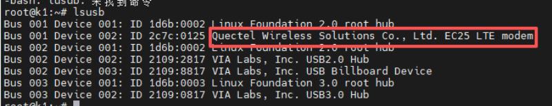
-
Use the AT command to query the module and SIM card status
AT+CGMM   //Module status
AT+CPIN?  //SIM card status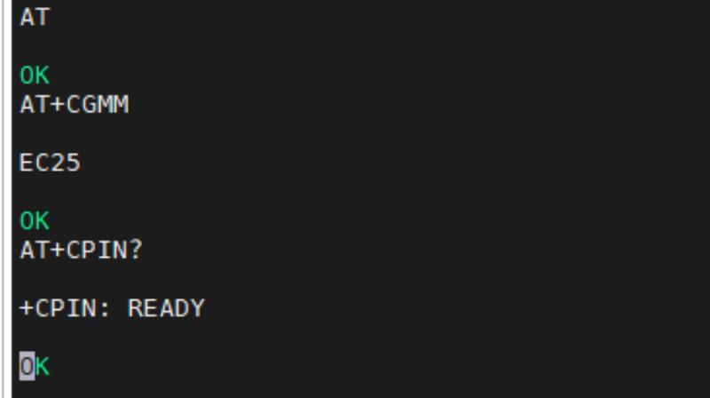
-
Use nmcli to enable the module for dialing.
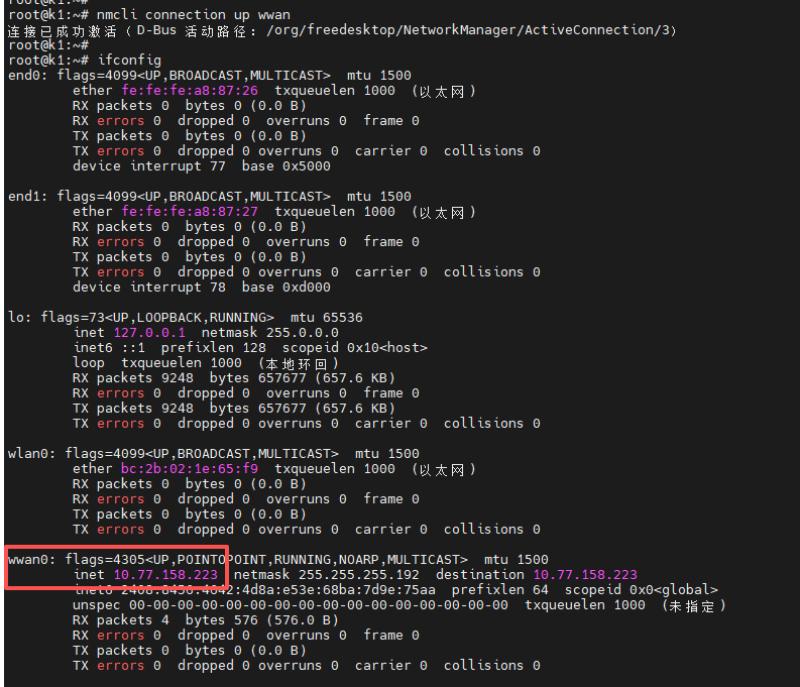
root@k1:~# nmcli connection delete wwan 成功删除连接 "wwan" (cf521d55-c9b0-48d3-96b7-d544cee4b054)。 root@k1:~# nmcli connection add type gsm ifname "*" con-name wwan apn cmnet 连接 "wwan" (cc1953ac-27d9-4bed-98c7-2256c6c6135a) 已成功添加。 root@k1:~# root@k1:~# root@k1:~# root@k1:~# nmcli connection up wwan 连接已成功激活(D-Bus 活动路径:/org/freedesktop/NetworkManager/ActiveConnection/3) -
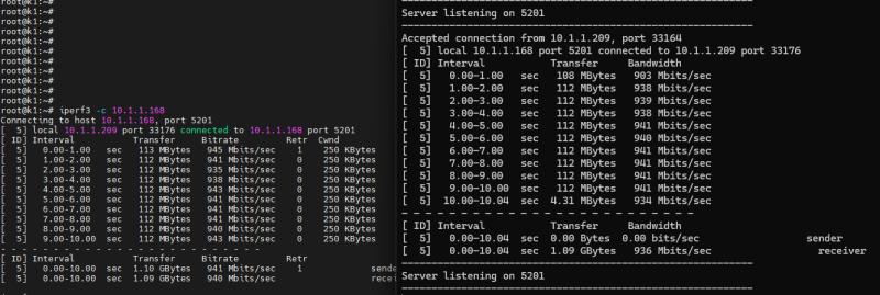
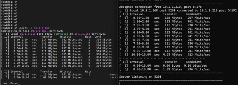
you can see that the wwan0 interface has been assigned an IP address.
-
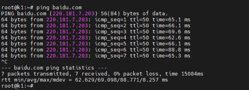
by using the ping command to test the external network, it can be seen that the system is now able to access the internet normally.
¶ Armbian Compilation
Perform the following three steps to complete the armbian image.
git clone [email protected]:BPI-SINOVOIP/armbian-build.git -b v24.04.30 v24.04.30
cd v24.04.30
./compile.sh build BOARD=bananapif3 BRANCH=legacy BUILD_DESKTOP=yes BUILD_MINIMAL=no DESKTOP_APPGROUPS_SELECTED= DESKTOP_ENVIRONMENT=gnome DESKTOP_ENVIRONMENT_CONFIG_NAME=config_base KERNEL_CONFIGURE=no RELEASE=mantic¶ RTC
| After the system is powered on, the RTC will automatically synchronize the system time. You can use commands to query the system time and the RTC time. The system time here is CST time, while the RTC shows UTC time. The difference of 8 hours is within the normal range. |
-
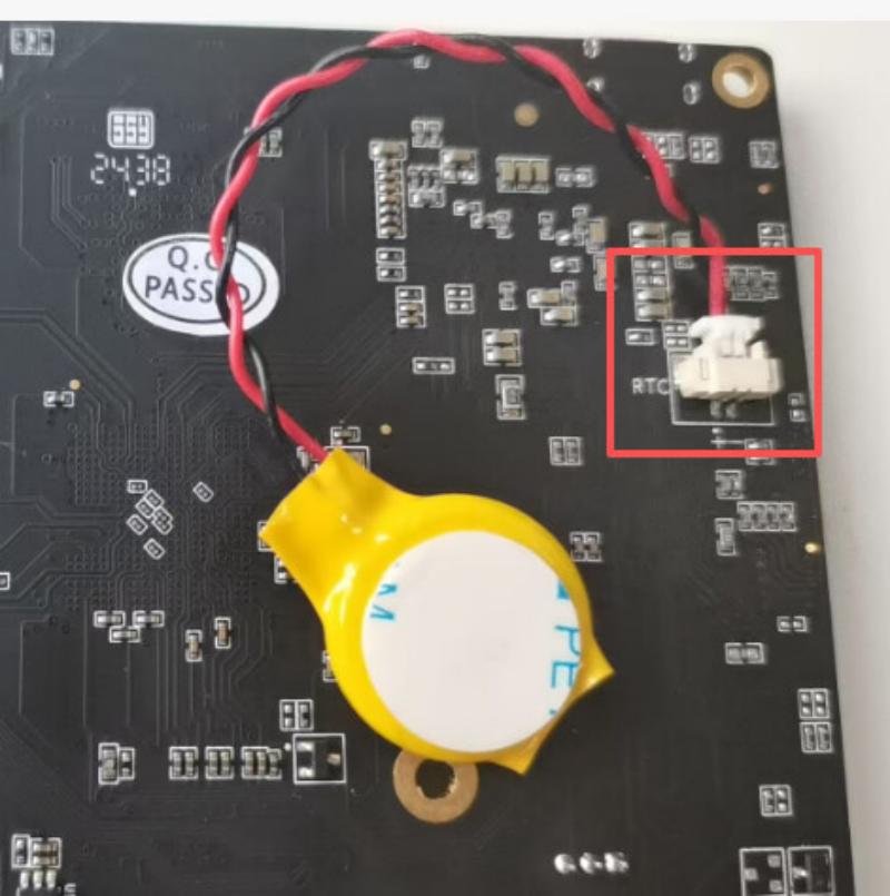
Connect the battery to the RTC interface of F3.Then Connect the power supply of BPI-F3 and turn on the power to start the device.Connect to the network to obtain real-time time.
root@k1:~# date 2025年 10月 11日 星期六 14:25:47 CST root@k1:~# cat /sys/class/rtc/rtc0/{date,time} 2025-10-11 06:25:59 -
Turn off the power supply and disconnect the network cable. Wait for a while. After powering on again, it was confirmed that the RTC time was operating correctly, but the system time could not be synchronized as the network cable was disconnected.
root@k1:~# date
2025年 10月 11日 星期六 14:02:48 CST
root@k1:~# cat /sys/class/rtc/rtc0/{date,time}
2025-10-11
06:38:37
¶ FAN
echo 0 > /sys/class/pwm/pwmchip1/export
echo 100000 > /sys/class/pwm/pwmchip1/pwm0/period
echo 50000 > /sys/class/pwm/pwmchip1/pwm0/duty_cycle
echo normal > /sys/class/pwm/pwmchip1/pwm0/polarity
echo 1 > /sys/class/pwm/pwmchip1/pwm0/enable