The black screws are M3 x 6 and the silver screws are M2.5 x 6.
¶ Introduce
¶ Shell
Aluminum housing with 14 antenna holes. Can perfectly meet your needs.
We have a screw knife in the packaging, 10 cross -head black screws (4 pre -installed on the shell), 6 cross -headed silver screws, and four foot pads.
¶ Heat sink
The heat sink kit (one of the two choices; the two can be used when you do not insert the WiFi7 card, but the WiFi7 card is hot after inserting the WiFi7 card. It is recommended to use a fan with a fan, and cooperate with the latest fan -managed Image to avoid overheating restart)
-
Without a fan heat sink
38*38mm universal heat sink, with glue nails
Heating silicone pad (10*5*1.6mm 2PCS ; 21*21*1mm 1PCS)
-
Customized heat sink with fan
¶ BPI-R4-NIC-BE14 kit
Contains one BPI-R4-NIC-BE14, three SMA female male pins (L=150MM-IPEX-1 generation), three SMA female male pins (L=230MM-IPEX-1 generation), and three thermally conductive silicone pads .(For fixing screws, please use the silver cross-head screws M2 x 5 provided when you purchase BPI-R4)
BPI-R4-NIC-BE14
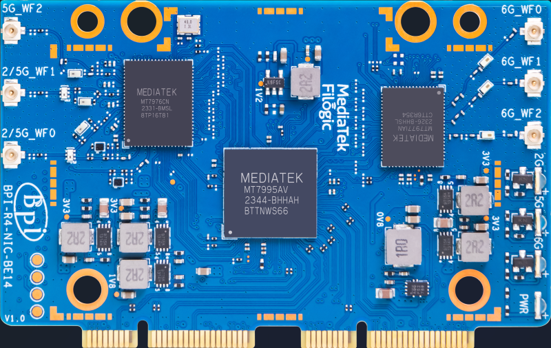
¶ 5G module
Four IPEX-4 generation SMA (L=100MM) and four 5G antennas.(For fixing screws, please use the silver cross-head screws M2 x 5 provided when you purchase BPI-R4)
¶ Accessory installation
-
First, insert the BPI-R4-NIC-BE14 (BE14 for short) into the miniPCIe socket under the BPI-R4-MAIN and secure it with two M2*5 screws.
-
Then attach two 13*10*2mm and one 14*14*2mm thermally conductive silicone pads to the three ICs of BE14 respectively.
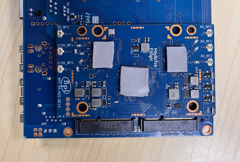
-
Insert the 6 coaxial cables into the corresponding U.FL sockets. (Use the same length of wire on the same side)
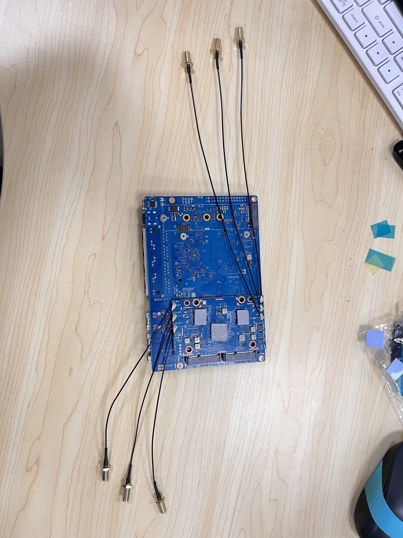
-
Remember to turn SW4 to the ON position.
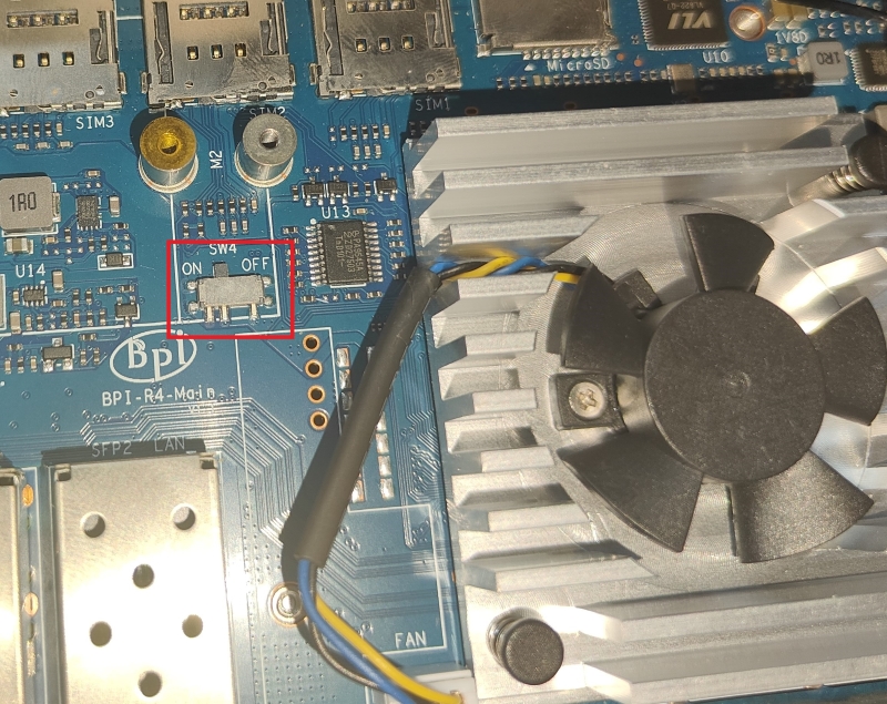
-
Install the board into the bottom case and adjust the position of the antenna so that it is not pressed. Use four M2.5x6 screws to secure it.
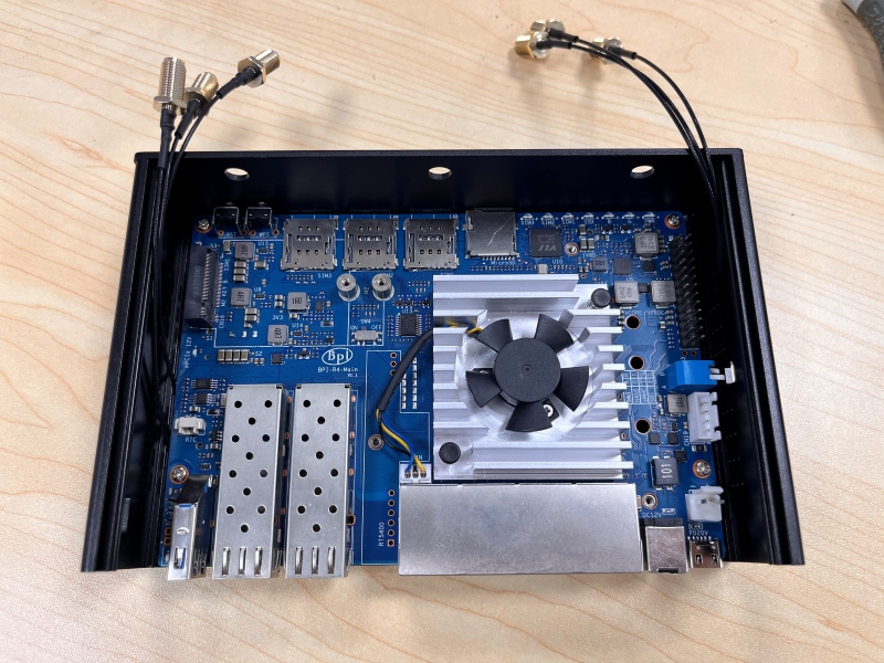
-
Install the heat sink. If it has a fan, plug in the fan power cord.
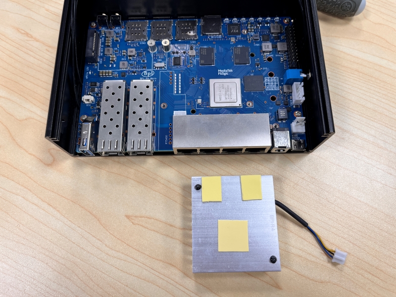
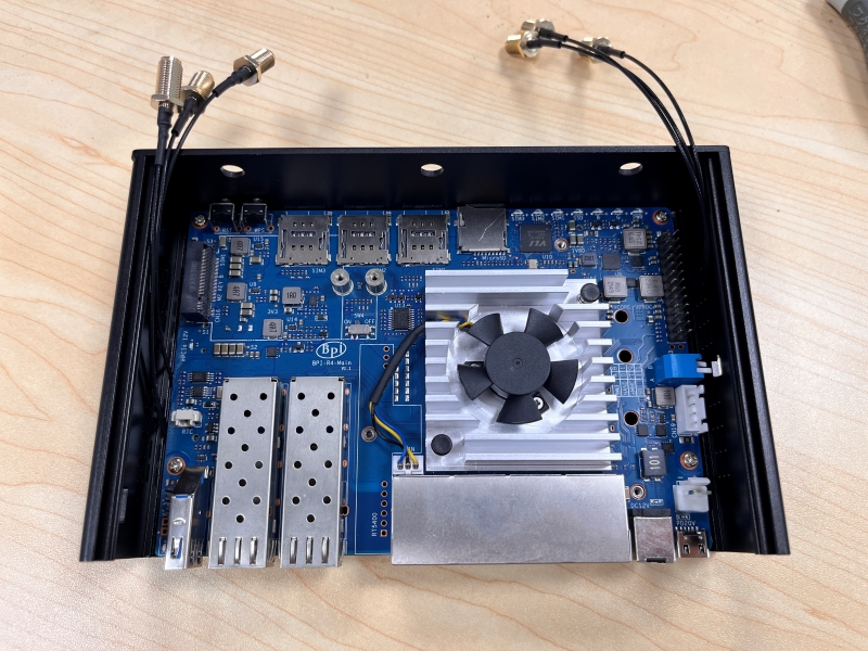
-
Connect the 6 antennas to ANT2/3/4/6/7/8 respectively.
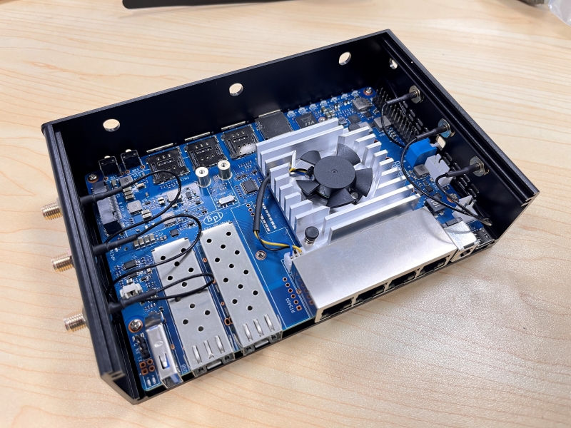
-
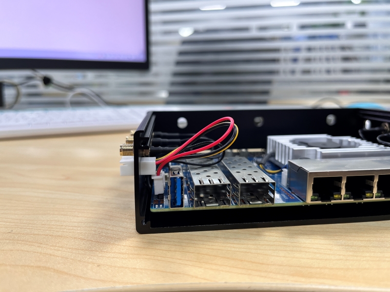
To facilitate debugging, you can purchase a serial port extension cable. In this way, there is no need to disassemble the shell for subsequent debugging. (Extension cords need to be purchased by yourself, we do not provide this)
-
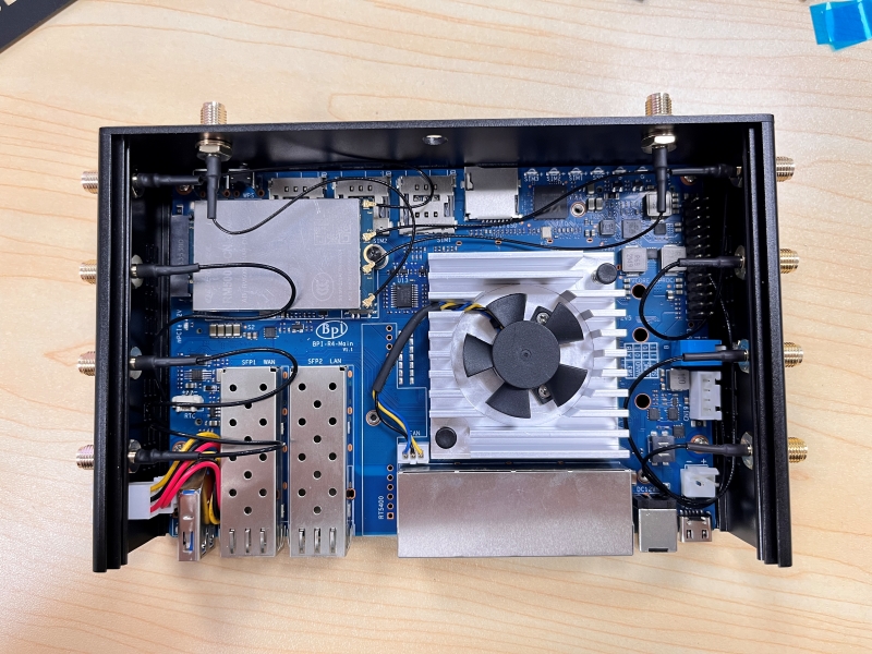
Insert the 5G module into the M.2 KEY B interface and secure it with M2*5 screws.
-
Insert the four SMA female pins (L=100MM IPEX-4 generation) coaxial cables and fix them on the shell ANT1/5 and the two SMA holes on the front panel.
-
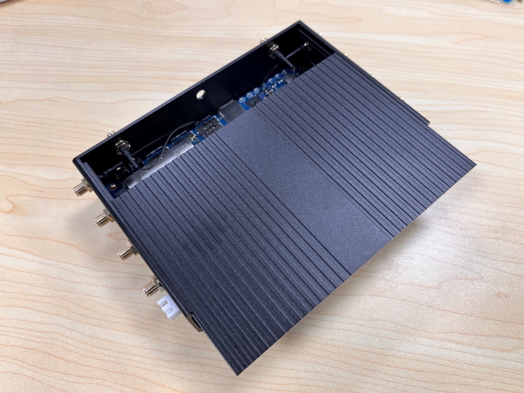
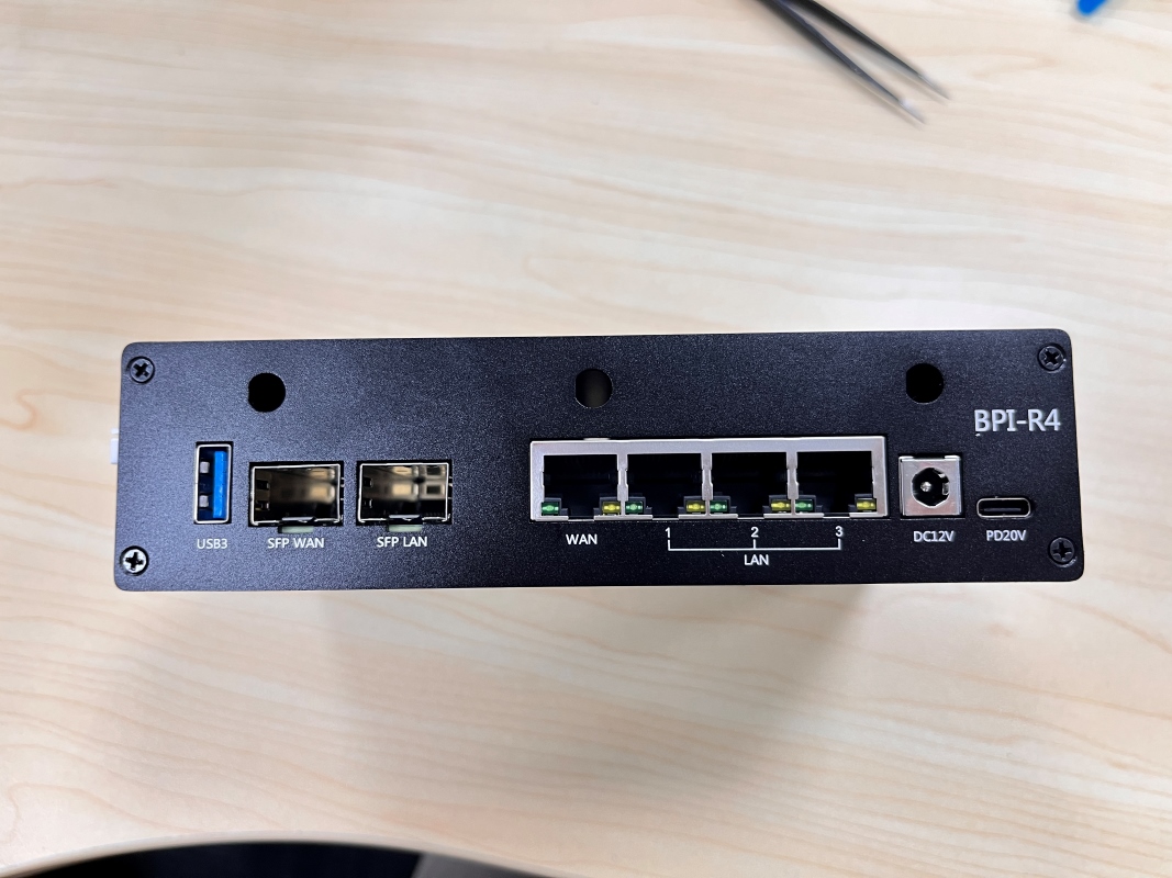
Insert the upper cover into the bottom case along the guide rails, and fix the covers on both sides with 8 black flat-head M3x6 screws.(It is not recommended to insert the SIM card tray when no card is installed, as it is very likely to damage the SIM card holder)
-
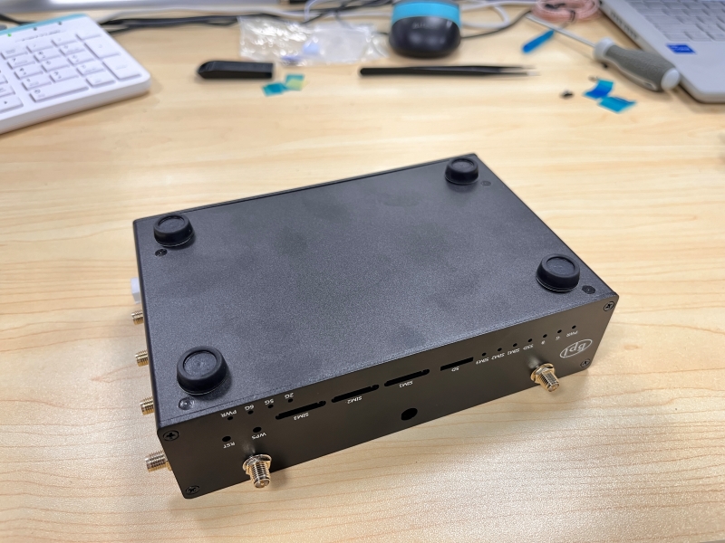
Install 4 silicone feet on the bottom.
-
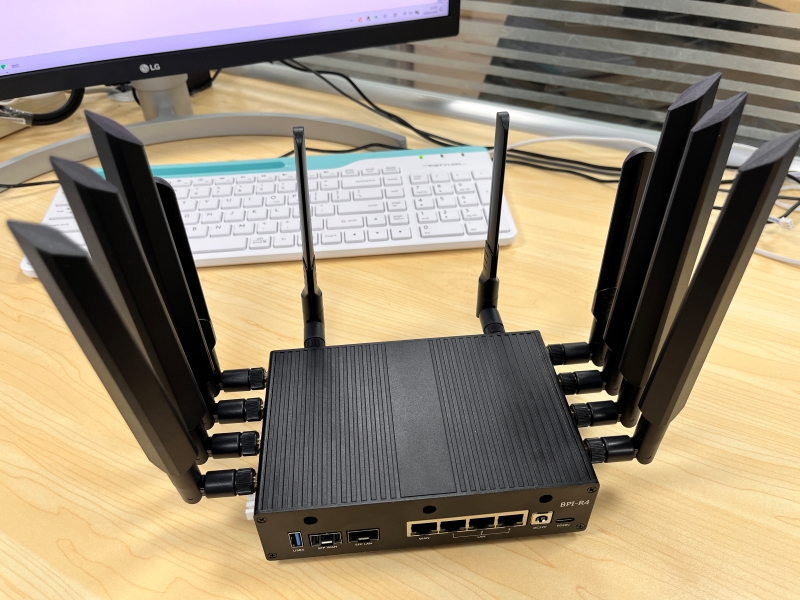
Install the WiFi and 5G antennas into the corresponding SMA seats respectively.
-
Assembly is complete. Next, you can plug in the SFP module, TF card, network cable, U disk, etc. according to your needs. Then power on and start.