¶ Introduction
The Banana Pi BPI-W3 single board computer is designed and developed by bananapi team for professional and enterprise users, powered by Rockchip RK3588 SoC quad ARM Cortex-A76 and quad Cortex-A55 consists of an eight-core CPU processor with dynamic frequency scaling up to 2.4GHz. Embedded high -performance 3D and 2D image acceleration module, AI accelerator NPU with a built -in 6 TOPS computing power.
| More Infomation: Banana Pi BPI-W3 |
¶ Development Prepare
¶ Tool Preparation
-
BPI-W3 main board
-
Power supply (choose one of three)
-
USB Type-C PD 2.0 supporting 9V/2A, 12V/2A, 15V/2A and 20V/2A
-
DC 12V adapter, 2.5mm
-
PoE 12V
-
-
System installation (choose one of two)
-
MicroSD /TF card boot
-
MicroSD card/TF card, Class 10 or above, at least 8GB SDHC, and card reader
-
Here are some high speed TF cards tested and verified by the ArmSoM team:
-
SanDisk 32GB TF (MicroSD) (developer recommended)
-
SanDisk 32GB TF (MicroSD) Car Recorder & Security Monitoring Special Storage Card (recommended for long-term operation)
-
Sandisk TF 8G Class10 microSD
-
Sandisk TF 128G Class10 microSD XC TF 128G 48MB/S
-
-
-
Onboard eMMC boot
-
USB A to C data cable, to write images to the ArmSoM-W3 eMMC or use fastboot/adb commands over the type C port. You need a USB A to type C data cable connecting the ArmSoM-W3 and PC.
-
-
¶ Optional Accessories
-
USB keyboard & mouse
-
HDMI display and HDMI cable
-
The BPI-W3 is equipped with a full-size HDMI port, with maximum support for 8K@60 display.
-
HDMI EDID is used to determine the best display resolution. This resolution will be selected on displays and TVs that support 1080p (or 4K/8K). If not for 1080p, EDID will find the next available resolution.
-
-
Ethernet cable
-
The BPI-W3 supports ethernet internet access, up to 2.5G.
-
The network cable is used to connect the BPI-W3 to the local network and internet.
-
-
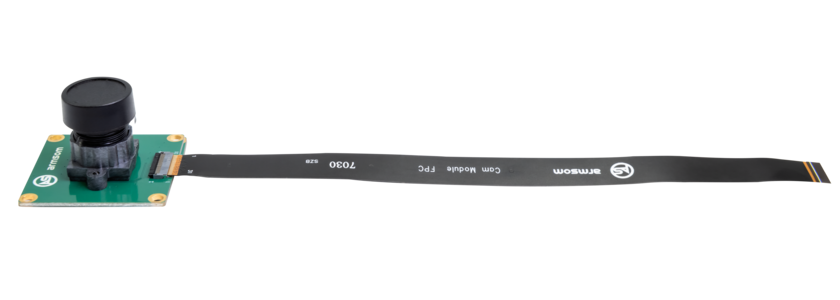
Camera module
-
The BPI-W3 supports camera capabilities.
-
It is recommended to use the imx415 module, available through the Baanana Pi Official store.
-
-
LCD display
-
The BPI-W3 supports LCD display capabilities.
-
It is recommended to use the Display 10.1 HD, available through the Official store.
-
-
Audio cable
-
Standard 3.5mm jack can be used to play audio via speakers or headphones.
-
-
WiFi/Bluetooth card
-
supports common wireless modules on the market, please check the Wireless section of the supported list.
-
It is recommended to use RTL8852be, AP6256
-
-
USB-A to USB-C data cable
¶ Android
¶ Install Image with Usb Download Tool
-
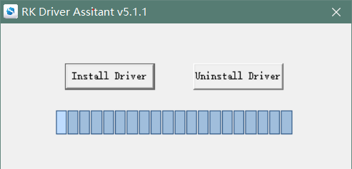
Download and install Rockchip USB driver
-
Download Rockchip USB Download Tool
This tool defaults language is Chinese. you can change it to English after extract the package. Open RKDevTool_Release_v2.84/config.ini with an text editor (like notepad). The starting lines are: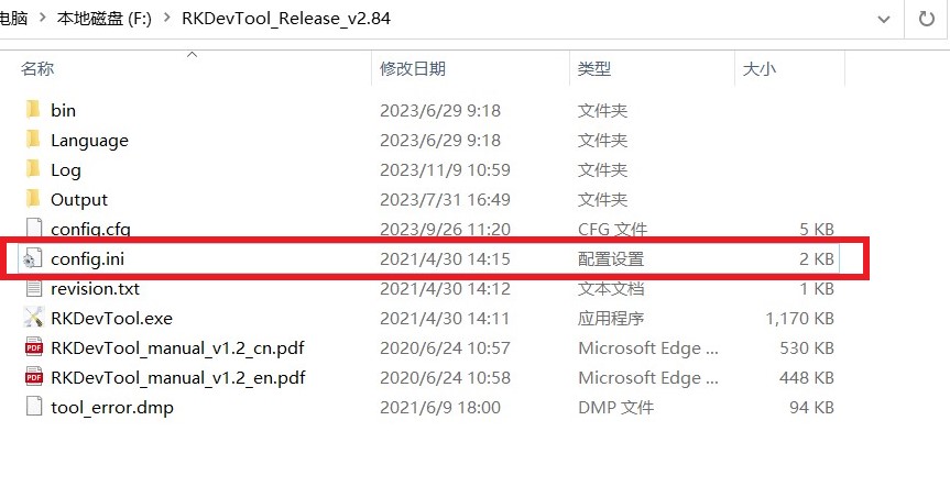
#Language Selection: Selected=1(Chinese); Selected=2(English) [Language] Kinds=2 Selected=1 LangPath=Language\ -
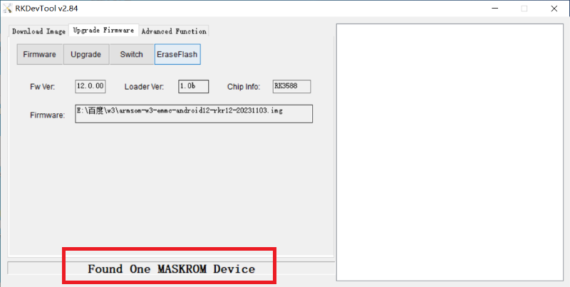
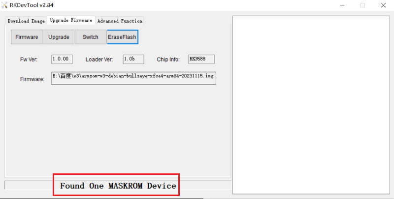
Open RKDevTool.exe, Switch to the “Upgrade Firmware” page. Press the “Firmware” button to open the image file to be upgraded. The upgrade tool displays detailed firmware information.
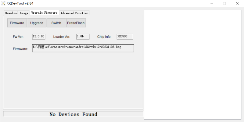
-
While holding down the MASKROM key, connect w3 to PC using a type-c cable.(If there is already an image in emmc, hold down the MASKROM key while pressing the REST key.)
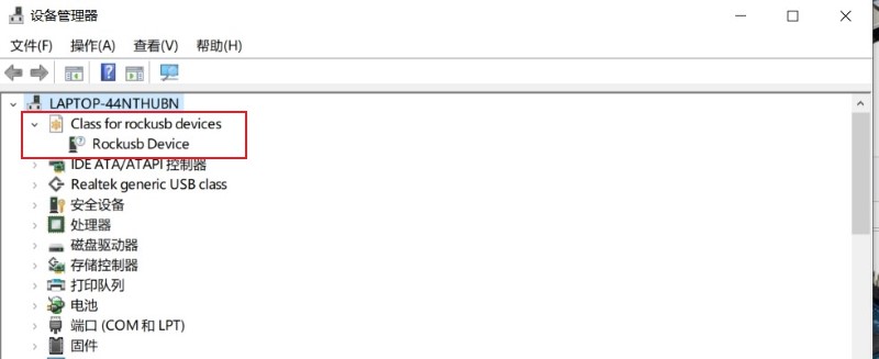
-
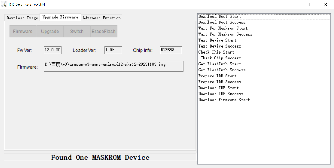
Press the “upgrade” button to start the upgrade.
-
If the upgrade fails, you can try to erase the Emmc by pressing the EraseFlash button first, and then upgrade image again.
¶ Linux
¶ Install Image to sd card 1
| Use this method for Ubuntu and Armbian images. |
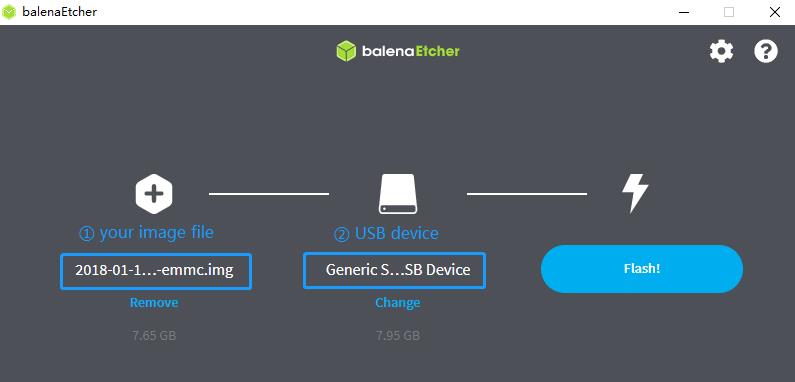
Install Image with Balena Etcher.
Balena Etcher is an opensource GUI flash tool by Balena, Flash OS images to SDcard or USB drive.
-
Click on "Flash from file" to select image.
-
Click on "Select target" to select USB device.
-
Click on "Flash!" Start burning.
¶ Install Image to sd card 2
| Debian images use this method. |
-
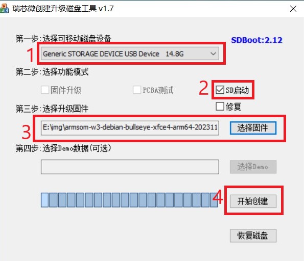
Download Rockchip SD Disk Tool.
-
Insert card reader to Windows PC, 8GB sdcard size at least.
-
Run SD_Firmware_Tool, check the “SD card startup” box and select the correct removable disk device, Choose firmware image, then Click Create button to make it and wait until it is finshed.
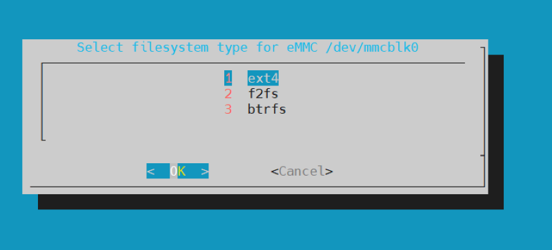
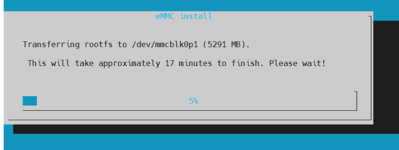
¶ Install Image to eMMC 1
| Ubuntu |
-
Copy the image to a USB drive. Start w3 with an SD card and insert a USB drive at the same time.
-
Execute
mount /dev/sda1 /mnt
cd /mnt
sudo dd if=w3-ubuntu-xxxx.img of=/dev/mmcblk0 bs=10M
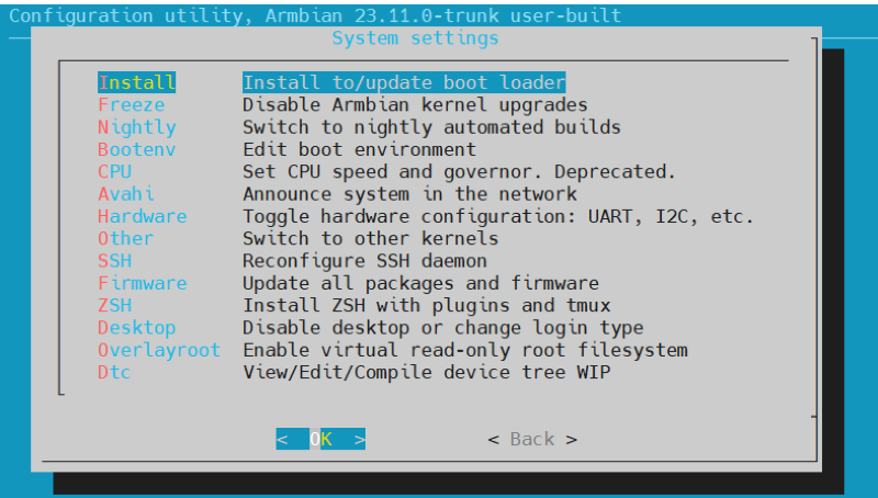
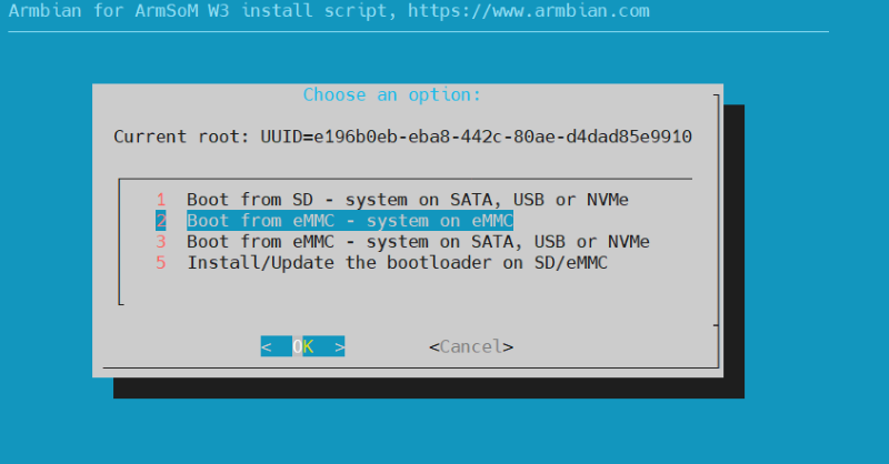
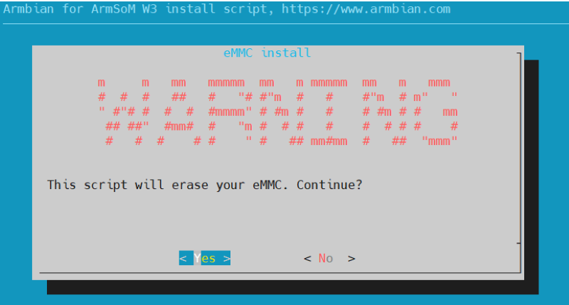
| Armbian |
-
Insert the SD card with the burned image into w3, then power on and start.
-
Execute
sudo armbian-config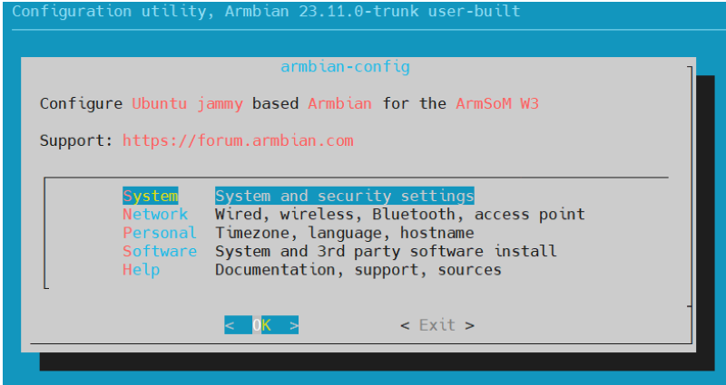

-
The last step is to shut down the computer. At this time, disconnect the power supply, remove the SD card, and power on again to boot from eMMC.
¶ Install Image to eMMC 2
| Debian images use this method. |
-
Download and install Rockchip USB driver
-
Download Rockchip USB Download Tool
This tool defaults language is Chinese. you can change it to English after extract the package. Open RKDevTool_Release_v2.84/config.ini with an text editor (like notepad). The starting lines are:
#Language Selection: Selected=1(Chinese); Selected=2(English) [Language] Kinds=2 Selected=1 LangPath=Language\ -
Open RKDevTool.exe, Switch to the “Upgrade Firmware” page. Press the “Firmware” button to open the image file to be upgraded. The upgrade tool displays detailed firmware information.

-
While holding down the MASKROM key, connect w3 to PC using a type-c cable.(If there is already an image in emmc, hold down the MASKROM key while pressing the REST key.)
-
Press the “upgrade” button to start the upgrade.

-
If the upgrade fails, you can try to erase the Emmc by pressing the EraseFlash button first, and then upgrade image again.
¶ 2.5G Ethernet
If you are using wired ethernet internet, please insert the network cable into the RJ45 port on the ArmSoM-W3, and then the wired connection prompt will pop up on the system desktop.
How to manually configure ethernet?
-
Switch to root user
sudo suUse the command -ifconfig to check if ethernet is working properly, then showing the eth0 or enP4p65s0 network card and ethernet IP address. Also use the ping tool to test connectivity to the network.
ifconfig
ping www.baidu.com-
If unable to ping, please try:
$ sudo dhclient eth0or
$ sudo dhclient enP4p65s0¶ Audio
View the sound cards in the system.
armsom@armsom-w3:/# aplay -l
**** List of PLAYBACK Hardware Devices ****
card 0: rockchipdp0 [rockchip,dp0], device 0: rockchip,dp0 spdif-hifi-0 [rockchip,dp0 spdif-hifi-0]
 Subdevices: 1/1
 Subdevice #0: subdevice #0
card 1: rockchipes8316 [rockchip-es8316], device 0: fe470000.i2s-ES8316 HiFi es8316.7-0011-0 [fe470000.i2s-ES8316 HiFi es8316.7-0011-0]
  Subdevices: 1/1
  Subdevice #0: subdevice #0
card 3: rockchiphdmi0 [rockchip-hdmi0], device 0: rockchip-hdmi0 i2s-hifi-0 [rockchip-hdmi0 i2s-hifi-0]
  Subdevices: 1/1
  Subdevice #0: subdevice #0
card 4: rockchiphdmi1 [rockchip-hdmi1], device 0: rockchip-hdmi1 i2s-hifi-0 [rockchip-hdmi1 i2s-hifi-0]
  Subdevices: 1/1
Subdevice #0: subdevice #0¶ USB Interface
The BPI-W3 provides two USB 2.0 and two USB 3.0 ports.
¶ Type-C
The BPI-W3 features a full-featured USB Type‐C 3.0 port which supports up to 8K@30fps DP display.
¶ HDMI
The BPI-W3 has two HDMI output ports, both supporting CEC and HDMI 2.1, with maximum resolutions of 8Kp60 and 4Kp60 respectively.
| Please confirm the interface specifications of the HDMI cable before use. |
¶ HDMI IN
The BPI-W3 uses the native rk3588 hdmi rx interface.The hdmi in interface can be tested using v4l2 commands.
View all video nodes
ls /dev/video*¶ Find rk hdmirx device
Execute command v4l2-ctl -d to specify video node. Execute command -D to view node info. Check for rk_hdmirx device using driver name.
armsom@armsom-w3:/# v4l2-ctl -d /dev/video0 -D
Driver Info:
Driver name : rk_hdmirx
Card type : rk_hdmirx
Bus info : fdee0000.hdmirx-controller
Driver version : 5.10.66
Capabilities : 0x84201000
Video Capture Multiplanar
Streaming
Extended Pix Format
Device Capabilities
Device Caps : 0x04201000
Video Capture Multiplanar
Streaming
Extended Pix Format¶ Query resolution and image formats
Query current resolution and image formats:
armsom@armsom-w3:/# v4l2-ctl -d /dev/video17 --get-fmt-video
Format Video Capture Multiplanar:
Width/Height : 3840/2160
Pixel Format : 'NV16'
Field : None
Number of planes : 1
Flags : premultiplied-alpha, 000000fe
Colorspace : Unknown (1025fcdc)
Transfer Function : Unknown (00000020)
YCbCr Encoding : Unknown (000000ff)
Quantization : Default
Plane 0 :
Bytes per Line : 3840
Size Image : 16588800¶ Capture image files
Save image files to device and view with 7yuv etc:
v4l2-ctl --verbose -d /dev/video17 \
--set-fmt-video=width=3840,height=2160,pixelformat='NV16' \
--stream-mmap=4 --stream-skip=3 \
--stream-to=/data/4k60_nv16.yuv \
--stream-count=5 --stream-poll¶ RGB LED
The BPI-W3 has a power LED and user LED.
-
Power Indicator LED: The power LED is green. On the ArmSoM-W3 it is solid on by default when powered.
-
User Indicator LED: The user LED is blue. By default its blinking state shows a running kernel.
The user can control via commands:
armsom@armsom-w3:/# sudo su
root@armsom-w3:/# echo timer > /sys/class/leds/blue:status/trigger
root@armsom-w3:/# echo activity > /sys/clas¶ RTC
-
The BPI-W3 is equipped with an RTC IC hym8563.
-
First, insert the RTC battery to power the RTC IC.
| that we should keep the RTC battery in the RTC connector and confirm the rtc hym8563 device has been created |
armsom@armsom-w3:/#  dmesg | grep rtc
[    6.407133] rtc-hym8563 6-0051: rtc information is valid
[    6.412731] rtc-hym8563 6-0051: registered as rtc0
[ 6.413779] rtc-hym8563 6-0051: setting system clock to 2022-06-22T01:22:26 UTC (1655860946)Locating rtc0, then use the following commands to set system time and sync to rtc0.
armsom@armsom-w3:/# hwclock -r
2023-11-03 10:32:40.461910+00:00
armsom@armsom-w3:/# date
11/03/2023 Friday 10:33:12 UTC
armsom@armsom-w3:/# hwclock -w
armsom@armsom-w3:/# hwclock -r
armsom@armsom-w3:/# poweroffRemoving RTC battery, after 10mins or longer insert battery and boot ArmSoM-W3, check if RTC is in sync with system clock
armsom@armsom-w3:/# hwclock -r
2023-11-03 10:35:40.461910+00:00
armsom@armsom-w3:/# date
11/03/2023 Friday 10:36:01 UTC¶ Fan
The BPI-W3 is equipped with a 5V fan, using a 1.25mm connector
armsom@armsom-w3:/# echo 0 > /sys/devices/platform/fd8b0010.pwm/pwm/pwmchip*/export
armsom@armsom-w3:/# echo 10000 > /sys/devices/platform/fd8b0010.pwm/pwm/pwmchip*/pwm0/period
armsom@armsom-w3:/# echo 5000 > /sys/devices/platform/fd8b0010.pwm/pwm/pwmchip*/pwm0/duty_cycle
armsom@armsom-w3:/# echo inversed  > /sys/devices/platform/fd8b0010.pwm/pwm/pwmchip*/pwm0/polarity
armsom@armsom-w3:/# echo 1 > /sys/devices/platform/fd8b0010.pwm/pwm/pwmchip*/pwm0/enable
armsom@armsom-w3:/# echo 0 > /sys/devices/platform/fd8b0010.pwm/pwm/pwmchip*/pwm0/enable¶ M.2 Interface
The BPI-W3 provides two M.2 connectors:
There is an M.2 E Key connector on the front of the board with a 2230 mounting hole, providing PCIe 2.1 single-channel, USB, SATA, SDIO, PCM and UART signals, supporting standard industrial M.2 WiFi 6 modules.
Banana Pi recommends using RTL8852BE, AP6256. Installed in the BPI-W3 M.2 E slot and then it can get online after wifi setup.
# Load driver
armsom@armsom-w3:/# insmod system/lib/modules/rtkm.ko
armsom@armsom-w3:/# insmod system/lib/modules/rtkm.ko
armsom@armsom-w3:/# insmod /usr/lib/modules/rtk_btusb.ko
armsom@armsom-w3:/# lsmod

Module                  Size  Used by
8852be               4030464  0
rtkm                   16384  1 8852be
rtk_btusb 57344 0¶ WIFI
# 1. Switch to super user mode
armsom@armsom-w3:/# sudo su
# 2. Open the WIFI
root@armsom-w3:/# nmcli r wifi on
# 3. Scan WIFI
root@armsom-w3:/# nmcli dev wifi
# 4. Connect to WIFI network
root@armsom-w3:/# nmcli dev wifi connect "wifi_name" password "wifi_password"¶ BT
# 1. Activate bluetooth
armsom@armsom-w3:/# service bluetooth start
# 2. Enter to bluetoothctl
armsom@armsom-w3:/# bluetoothctl
# 3. Input the below commands to connect
armsom@armsom-w3:/# power on
armsom@armsom-w3:/# agent on
armsom@armsom-w3:/# default-agent
armsom@armsom-w3:/# scan on
armsom@armsom-w3:/# pair yourDeviceMACThere is an M.2 M Key connector on the back of the BPI-W3 with a quad-channel PCIe 3.0 interface. There is a standard M.2 2280 mounting hole on board that can deploy M.2 2280 NVMe SSDs.
| This M.2 interface does not support M.2 SATA SSDs. |
armsom@armsom-w3:/# mkdir temp
armsom@armsom-w3:/# mount /dev/nvme0n1 temp¶ MIC Recording
armsom@armsom-w3:~# arecord -D hw:1,0 -f S16_LE -t wav -c2 -r 16000 -d 3 t.wav
Recording WAVE 't.wav' : Signed 16 bit Little Endian, Rate 16000 Hz, Stereo
armsom@armsom-w3:~# aplay t.wav
Playing WAVE 't.wav' : Signed 16 bit Little Endian, Rate 16000 Hz, Stereo¶ Camera
The OV13850 module has the following features:
Pixel size: 1.12mm x 1.12mm 13 megapixels at 30 frames per second Image sizes are supported: 13.2MP (4224 x 3136), 10MP (4224 x 2376), 2K (2112 x 1568), EIS1080P (2112 x 1188), EIS 720P (1408 x 792), etc Two-wire Serial Bus Control (SCCB) Up to 4 channels MIPI serial output Operating temperature range: 0 ℃ ~ 60 ℃, storage temperature range: -30 ℃ ~ 80 ℃
¶ The OV13850 Camera Pin Define
PIN of The OV13850 Camera
| PIN of The OV13850 Camera | ||
|---|---|---|
PIN NO |
SYMBOL |
Description |
1 |
GND |
Ground |
2 |
CSI_RX_D3N |
Channel 3 differential negative signal |
3 |
CSI_RX_D3P |
Channel 3 differential positive signal |
4 |
GND |
Ground |
5 |
CSI_RX_D2N |
Channel 2 differential negative signal |
6 |
CSI_RX_D2P |
Channel 2 differential positive signal |
7 |
GND |
Ground |
8 |
NC |
NC |
9 |
NC |
NC |
10 |
GND |
Ground |
11 |
CSI_RX_D1N |
Channel 1 differential negative signal |
12 |
CSI_RX_D1P |
Channel 1 differential positive signal |
13 |
GND |
Ground |
14 |
CSI_RX_D0N |
Channel 0 differential negative signal |
15 |
CSI_RX_D0P |
Channel 0 differential positive signal |
16 |
GND |
Ground |
17 |
CSI_RX_CLK0N |
output clock differential negative signal |
18 |
CSI_RX_CLK1P |
output clock differential positive signal |
19 |
MIPI_VSYNC |
Frame synchronization signal |
20 |
MIPI_CLKOUT |
clock signal |
21 |
NC |
NC |
22 |
NC |
NC |
23 |
MIPI_CSI_PDN |
control signal |
24 |
I2C_SCL |
I2C clock signal |
25 |
I2C_SDA |
I2C data signal |
26 |
NC |
NC |
27 |
RESET |
Global reset signal |
28-29 |
VCC_3V3 |
VCCIO |
30-31 |
VCC_5V0 |
VCCIO |
¶ MIPI-CSI
¶ IMX415
The camera uses the IMX415 module. After connecting and powering on the camera module you can view the boot logs.
armsom@armsom-w3:/# dmesg | grep imx415
[    2.547754] imx415 3-001a: driver version: 00.01.08
[    2.547767] imx415 3-001a:  Get hdr mode failed! no hdr default
[    2.547819] imx415 3-001a: Failed to get power-gpios
[    2.547826] imx415 3-001a: could not get default pinstate
[    2.547831] imx415 3-001a: could not get sleep pinstate
[    2.547850] imx415 3-001a: supply dvdd not found, using dummy regulator
[    2.547918] imx415 3-001a: supply dovdd not found, using dummy regulator
[    2.547945] imx415 3-001a: supply avdd not found, using dummy regulator
[    2.613843] imx415 3-001a: Detected imx415 id 0000e0
[    2.613890] rockchip-csi2-dphy csi2-dphy0: dphy0 matches m00_b_imx415 3-001a:bus type 5
[   18.386174] imx415 3-001a: set fmt: cur_mode: 3864x2192, hdr: 0
[ 18.389067] imx415 3-001a: set exposure(shr0) 2047 = cur_vts(2250) - val(203)Use v4l2-ctl for image capture
armsom@armsom-w3:/# v4l2-ctl -d /dev/video11 --set-fmt-video=width=3840,height=2160,pixelformat=NV12 --stream-mmap=3 --stream-skip=60 --stream-to=/tmp/cif73.out --stream-count=3 --stream-pollUse gst-launch-1.0 for direct video recording
armsom@armsom-w3:/# gst-launch-1.0 v4l2src device=/dev/video11 ! video/x-raw,format=NV12,width=3840,height=2160, framerate=30/1 ! xvimagesink¶ OV13850
The camera uses the OV13850 module. After connecting and powering on the camera module you can view the boot logs.
root@armsom-w3:/# dmesg | grep ov13850
[    3.555686] ov13850 3-0010: driver version: 00.01.05
[    3.555722] ov13850 3-0010: Failed to get power-gpios, maybe no use
[    3.555762] ov13850 3-0010: Looking up avdd-supply from device tree
[    3.555773] ov13850 3-0010: Looking up avdd-supply property in node /i2c@feab0000/ov13850@10 failed
[    3.555794] ov13850 3-0010: supply avdd not found, using dummy regulator
[    3.555874] ov13850 3-0010: Looking up dovdd-supply from device tree
[    3.555883] ov13850 3-0010: Looking up dovdd-supply property in node /i2c@feab0000/ov13850@10 failed
[    3.555895] ov13850 3-0010: supply dovdd not found, using dummy regulator
[    3.555927] ov13850 3-0010: Looking up dvdd-supply from device tree
[    3.555935] ov13850 3-0010: Looking up dvdd-supply property in node /i2c@feab0000/ov13850@10 failed
[    3.555945] ov13850 3-0010: supply dvdd not found, using dummy regulator
[    3.555972] ov13850 3-0010: could not get default pinstate
[    3.555979] ov13850 3-0010: could not get sleep pinstate
[    3.561005] ov13850 3-0010: Detected OV00d850 sensor, REVISION 0xb2
[ 3.561027] rockchip-csi2-dphy csi2-dphy0: dphy0 matches m00_b_ov13850 3-0010:bus type 5Use v4l2-ctl for image capture
armsom@armsom-w3:/# v4l2-ctl -d /dev/video11 --set-selection=target=crop,top=0,left=0,width=2112,height=1568 --set-fmt-video=width=2112,height=1568,pixelformat=NV12 --stream-mmap=3 --stream-to=/nv12.bin --stream-count=1 --stream-pollUse gst-launch-1.0 for direct video recording
armsom@armsom-w3:/# gst-launch-1.0 v4l2src device=/dev/video11 ! video/x-raw,format=NV12,width=2112,height=1568, framerate=30/1 ! xvimagesink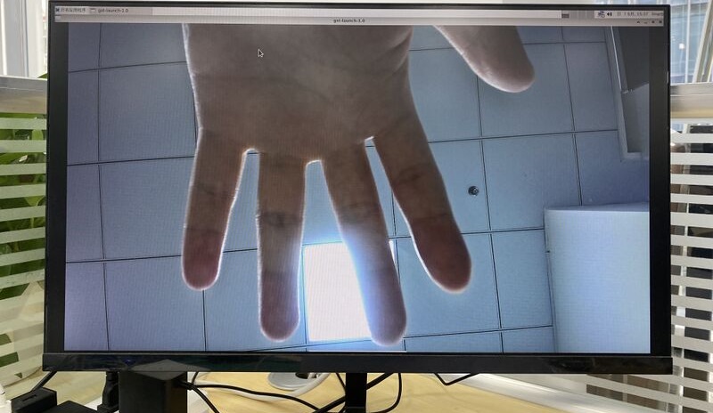
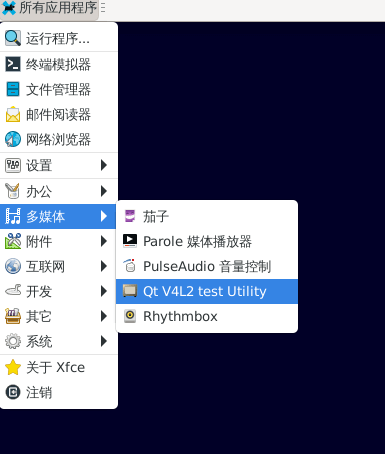
¶ USB3.0 Camera
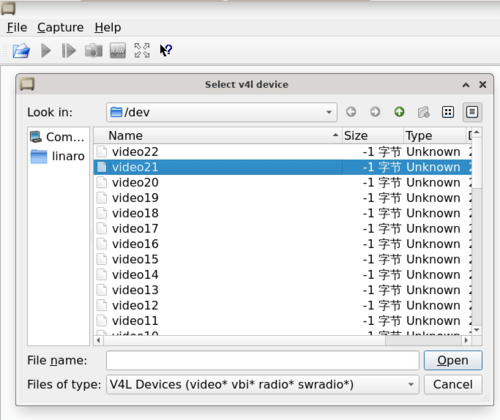
After connecting the usb3.0 camera, open the Qt V4L2 test Utility app for testing
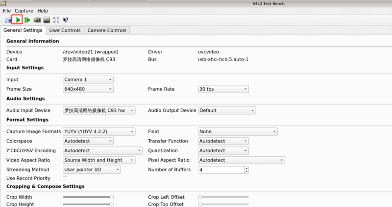
Open video node: video21
Click the camera button and you will see the camera screen
¶ MIPI DSI
The BPI-W3 has a maximum resolution up to 4K@60Hz
¶ NPU
DEMO video: https://www.youtube.com/watch?v=y7mYxn3rq0U
Prepare tools
-
Use the Ubuntu18.04 / Ubuntu20.04 operating system (OS).
-
An W3-PRO board
Preparation procedure
-
First make sure you have docker installed on your Ubuntu system,If not, refer to the Internet installation tutorial
-
We provide the source code and the docker image of the installed environment:docker image
-
Create a rknpu folder on the PC server and copy the firmware to the folder
rknpu/rknn-toolkit2-1.4.0/docker$ ls md5sum.txt rknn-toolkit2-1.4.0-cp36-docker.tar.gz rknn-toolkit2-1.4.0-cp38-docker.tar.gz -
Run the following command to run the docker image. After the Docker image is run, the bash environment of the image is displayed
docker run -t -i --privileged -v /dev/bus/usb:/dev/bus/usb rknn-toolkit2:1.4.0-cp38 /bin/bash -
Map examples code into a Docker environment by attaching "-v <host src folder>:<image dst folder>"Parameters, such as:
docker run -t -i --privileged -v /dev/bus/usb:/dev/bus/usb -v /your/rknn-toolkit2-1.x.x/examples:/examples rknn-toolkit2:1.x.x /bin/bash -
The code is synchronized after mapping
-
The rknn service needs to run on the development board
-
BOARD ARCH corresponds to the aarch64 directory on 64-bit Linux systems and to the armhf directory on 32-bit systems
-
adb push all files in Linux/rknn server/${B0ARD_ ARCH}/usr/bin/ to /usr/bin
-
adb push Linux/librknn api/${BOARD ARCH}/ librknrnt. so to /usr/1ib
-
Access the serial port terminal of the board and run the following command
chmod +x /usr/bin/rknn server
chmod +X /usr/bin/start_ rknn.sh
chmod +X /usr/bin/restart rknn.sh
restart_ rknn. sh
-
Run program
-
Execute adb devices in the docker image first, remembering the adb ID number
-
Go to /examples/onnx/yolov5 and change test.py
ret = rknn.init_runtime(target='rk3588', device_id=DEVICE_ID, perf_debug=True,eval_mem=True) outputs = rknn.inference(inputs=[img]) ret = rknn.eval_perf(inputs=[img], is_print=True) cv2.imwrite("result.jpg", img_1) -
The above four functions are not added
-
Run python3 test.py
¶ LED
-
On BPI-W3 three-color LED is configured as LED class device. When the blue LED is not active a green LED will show to indicate the board has power. You can control the behavior mode of the blue LED by writing to /sys/class/leds/blue:status/trigger. By default only root users can write to the device. The default mode of the blue LED is heartbeat.
linaro@linaro-alip:/home/linaro# sudo su // linaro password root@linaro-alip:/home/linaro# echo timer > /sys/class/leds/blue:status/trigger root@linaro-alip:/home/linaro# echo activity > /sys/class/leds/blue:status/trigger -
You can use cat on the trigger property to list all the available LED modes. The value in brackets is the currently active mode.
root@linaro-alip:/home/linaro# cat /sys/class/leds/blue:status/trigger none rfkill-any rfkill-none kbd-scrolllock kbd-numlock kbd-capslock kbd-kanalock kbd-shiftlock kbd-altgrlock kbd-ctrllock kbd-altlock kbd-shiftllock kbd-shiftrlock kbd-ctrlllock kbd-ctrlrlock tcpm-source-psy-4-0022-online mmc2 mmc1 timer oneshot disk-activity disk-read disk-write ide-disk mtd nand-disk heartbeat backlight gpio cpu cpu0 cpu1 cpu2 cpu3 cpu4 cpu5 cpu6 cpu7 mmc0 [activity] default-on transient flash torch panic netdev rfkill0 -
In the None mode, writing to /sys/class/leds/blue:status/brightness can manually control the status of the blue LED.
root@linaro-alip:/home/linaro# echo none > /sys/class/leds/blue:status/trigger root@linaro-alip:/home/linaro# echo 1 > /sys/class/leds/blue:status/brightness root@linaro-alip:/home/linaro# echo 0 > /sys/class/leds/blue:status/brightness -
red light is the same, class device /sys/class/leds/red:status/trigger
¶ RTC Device
BPI-W3 is equipped with one RTC IC hym8563
-
Firstly, plug in RTC battery to give power to RTC IC. Please note that we should keep the RTC battery in the RTC connector.
-
Secondly,Check whether the driver is successfully loaded.
root@linaro-alip:~# dmesg | grep rtc [ 3.149263] rtc-hym8563 6-0051: rtc information is valid [ 3.154624] rtc-hym8563 6-0051: registered as rtc0 [ 3.155646] rtc-hym8563 6-0051: setting system clock to 2021-01-01T12:00:05 UTC (1609502405) -
Finally, check whether you can view and set the time.
root@linaro-alip:~# hwclock -r
2022-08-07 13:38:24.370866+00:00
root@linaro-alip:~# date
2022年 08月 07日 星期日 13:38:41 UTC
root@linaro-alip:~# hwclock -w
¶ Others
¶ NPU usage
YouTube video: https://youtu.be/y7mYxn3rq0U
¶ Prepare tools
-
Use the Ubuntu18.04 / Ubuntu20.04 operating system (OS).
-
An W3-PRO board
¶ Preparation procedure
First make sure you have docker installed on your Ubuntu system,If not, refer to the Internet installation tutorial
We provide the source code and the docker image of the installed environment:docker image
Create a rknpu folder on the PC server and copy the firmware to the folder
rknpu/rknn-toolkit2-1.4.0/docker$ ls
md5sum.txt rknn-toolkit2-1.4.0-cp36-docker.tar.gz rknn-toolkit2-1.4.0-cp38-docker.tar.gzRun the following command to run the docker image. After the Docker image is run, the bash environment of the image is displayed
docker run -t -i --privileged -v /dev/bus/usb:/dev/bus/usb rknn-toolkit2:1.4.0-cp38 /bin/bashMap examples code into a Docker environment by attaching "-v <host src folder>:<image dst folder>"Parameters, such as:
docker run -t -i --privileged -v /dev/bus/usb:/dev/bus/usb -v /your/rknn-toolkit2-1.x.x/examples:/examples rknn-toolkit2:1.x.x /bin/bashThe code is synchronized after mapping
The rknn service needs to run on the development board
BOARD ARCH corresponds to the aarch64 directory on 64-bit Linux systems and to the armhf directory on 32-bit systems
 adb push all files in Linux/rknn server/${B0ARD_ ARCH}/usr/bin/ to /usr/bin
adb push Linux/librknn api/${BOARD ARCH}/ librknrnt. so to /usr/1ibAccess the serial port terminal of the board and run the following command
 chmod +x /usr/bin/rknn server
 chmod +X /usr/bin/start_ rknn.sh
 chmod +X /usr/bin/restart rknn.sh
restart_ rknn. sh¶ Run program
Execute adb devices in the docker image first, remembering the adb ID number
Go to /examples/onnx/yolov5 and change test.py
ret = rknn.init_runtime(target='rk3588', device_id=DEVICE_ID, perf_debug=True,eval_mem=True)
outputs = rknn.inference(inputs=[img])
ret = rknn.eval_perf(inputs=[img], is_print=True)
cv2.imwrite("result.jpg", img_1)The above four functions are not added
Run python3 test.py