¶ 开发准备
在开始使用 香蕉派 BPI-M7S产品之前,请准备好以下物品
¶ 工具准备
-
电源
-
系统安装(二选一)
-
板载eMMC启动
-
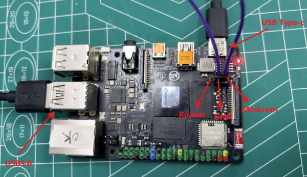
USB Type-c线供电、USB 双公头线烧录,从 USB3.0 端口在Sige7s上写入镜像,您需要使用USB 双公线连接 Sige系列和 PC,同时使用USB Type-c线连接Sige7s的type-c口供电。
-
-
MicroSD卡/TF卡启动
-
MicroSD卡/TF卡,Class 10或以上至少8GB SDHC 和 读卡器
-
以下是经过ArmSoM团队测试验证的高速TF卡
-
SanDisk 32GB TF(MicroSD)(开发者推荐)
-
SanDisk 32GB TF(MicroSD) 行车记录仪&安防监控专用存储卡(长期运行推荐)
-
闪迪 TF 8G Class10 microSD
-
闪迪 TF 128G Class10 microSD XC TF 128G 48MB/S:
-
-
-
您可以将 Sige 设置为带有桌面的交互式计算机,也可以将其设置为仅可通过网络访问的无头计算机。要将 Sige 设置为Headless计算机,您在初次安装操作系统时配置主机名、用户帐户、网络连接和 SSH 。如果您想直接使用 Sige,则需要以下附加配件:
¶ 可选配件
-
键盘 & 鼠标
-
HDMI显示器、DP 显示器、 HDMI线和 DP 线
-
Ethernet 线(网线)
-
摄像头模块
-
推荐使用 imx219 模组。
-
-
LCD显示屏
-
推荐使用微雪7寸 800×480 LCD 屏。
-
-
3.5mm带麦克风功能有线耳机。
¶ 电源
下表显示了为BPI-M7S 供电所需的电源规格。您可以使用任何提供正确电源模式的高质量电源。
| 产品 | 推荐电源(电压/电流) | 供电模式 |
|---|---|---|
BPI-M7S |
5V/3A |
USB Type-C |
将电源插入标有“PWR IN”的端口, 请确保使用正确端口!
登录系统所需账号:
| 用户名 | 密码 |
|---|---|
root |
root |
¶ 烧录方式选择
BPI-M7S 支持从emmc启动或SD卡启动,下面介绍将固件烧录到emmc或SD卡两种方式,以及如何擦除SPIFlash
¶ 将固件烧录到emmc
BPI-M7S 进入烧录模式需要按如下图方式短接,若要进入Maskrom模式则将Maskrom引脚与GND引脚短接,若要进入Loader模式则将Recovery引脚与GND引脚短接。
BPI-M7S 烧录使用USB双公线,一端接板载USB3.0接口,另一端接电脑端,同时接USB Type-C线给开发板供电。
-
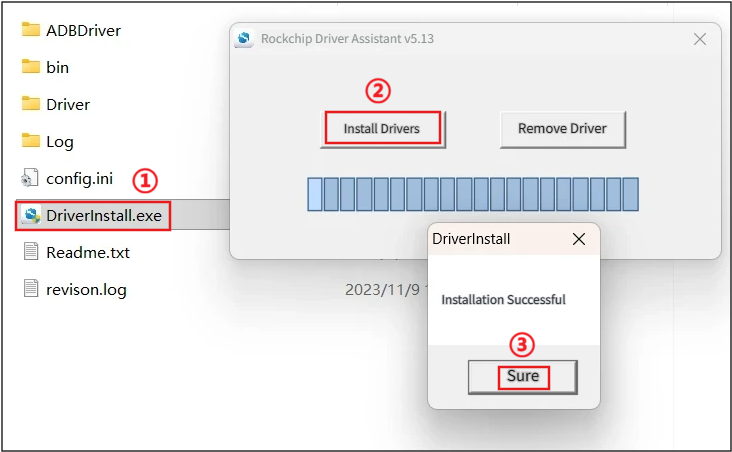
1. 按上述操作连接好以后,我们先安装USB驱动,打开RK驱动助手(DriverAssitant),执行①②③操作:
-
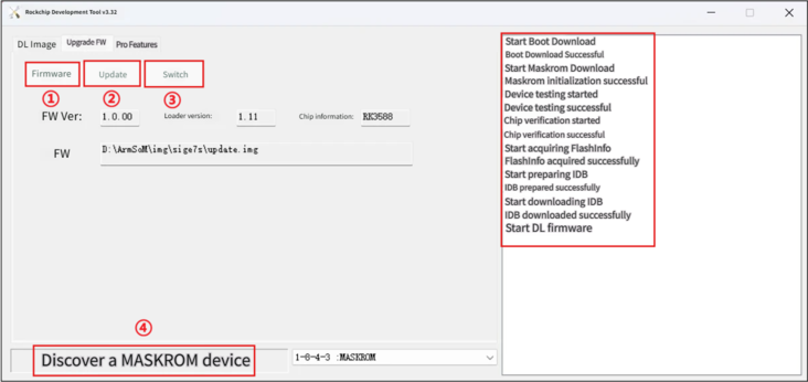
2. 安装完驱动后,打开烧录工具RKDevTool,观察④处识别为哪种模式,若显示为Maskrom模式或Loader模式,则可以点击①处选择固件,然后点击②处升级,直到右边信息栏显示固件升级完成即可
-
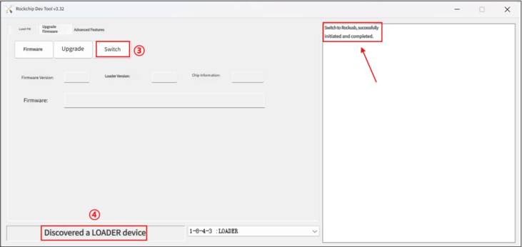
3. 若上面④处显示“发现一个ADB设备”,想要切换为烧录模式,点击图中的③切换,直到显示“切换Rockusb成功”后, 等待一会,即可看到④处显示为Maskrom模式或Loader模式,此时即可回到第二步升级固件操作
¶ 将固件烧录到SD卡
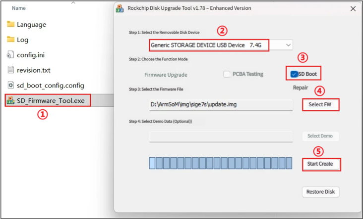
将SD卡插入SD读卡器,接入电脑后,双击运行SD_Firmware_Tool.exe,执行①②③操作:
¶ 擦除SPIFlash
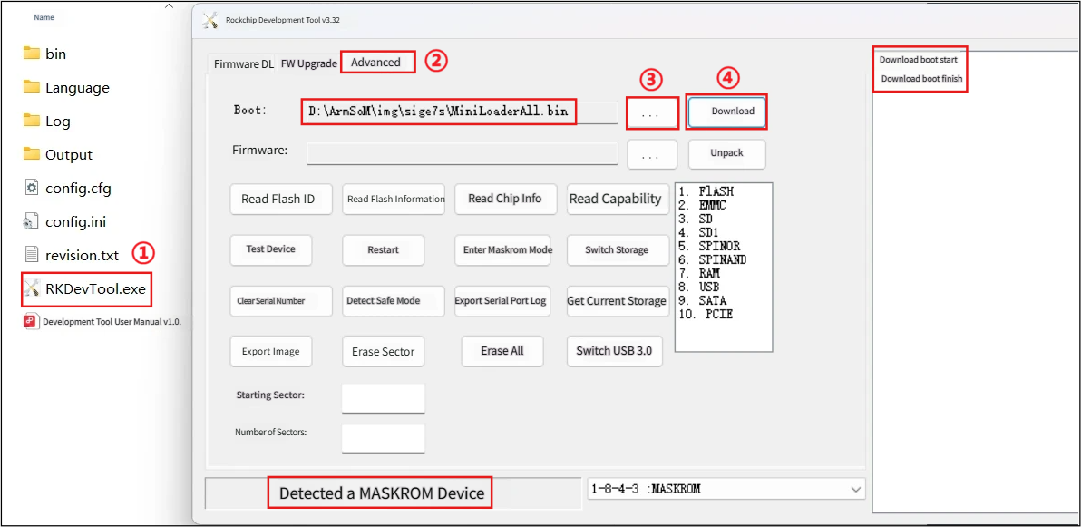
有时可能会遇到固件升级失败或异常、eMMC或SPI Nor Flash中残留的引导数据干扰了新系统的启动时,我们可以尝试先擦除Flash数据来强制设备进入Maskrom模式,然后重新烧录固件,可以按照如下方式操作:
-
1. ①打开烧录工具RKDevTool,②选择高级功能,③选择MiniLoaderAll.bin固件,④点击下载,等待下载完成即可
-
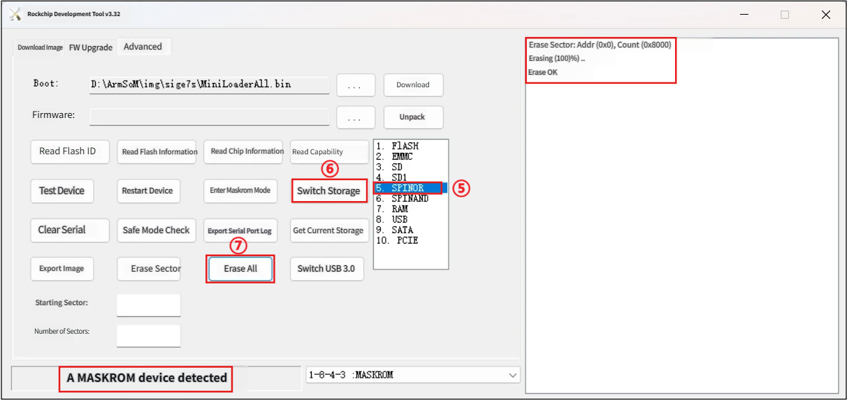
2. ⑤选择存储设备为 SPINOR,⑥点击切换存储,⑦点击擦除所有,等待擦除完毕即可
¶ 接口使用
¶ 调试串口
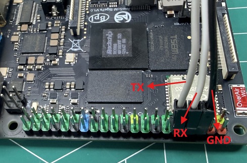
如下所示连接 USB 转 TTL 串口线到底板上40pin座子处:
| BPI-M7S | 连接 | 串口模块 |
|---|---|---|
GND(Pin6) |
--→ |
GND |
TX(Pin8) |
--→ |
RX |
RX(Pin10) |
--→ |
TX |
|
串口通讯参数 * 波特率:1500000 * 数据位:8 * 停止位:1 * 校验位:无 * 流控:无 |
¶ 以太网口
-
1. 首先将网线的一端插入 ArmSoM-Sige7s 的以太网接口,网线的另一端接入路由器,并确保 网络是畅通的
-
2. 系统启动后会通过 DHCP 自动给以太网卡分配 IP 地址,不需要其他任何配置
-
3. 在ArmSoM-Sige7s 的 Linux 系统中查看 IP 地址的命令如下所示,其中enP4p65s0就是以太网卡设备名称
armsom@armsom:~$ ip a
1: lo: <LOOPBACK,UP,LOWER_UP> mtu 65536 qdisc noqueue state UNKNOWN group default qlen 1000
    link/loopback 00:00:00:00:00:00 brd 00:00:00:00:00:00
    inet 127.0.0.1/8 scope host lo
       valid_lft forever preferred_lft forever
    inet6 ::1/128 scope host noprefixroute
       valid_lft forever preferred_lft forever
2: dummy0: <BROADCAST,NOARP> mtu 1500 qdisc noop state DOWN group default qlen 1000
    link/ether e2:98:22:4b:3e:f1 brd ff:ff:ff:ff:ff:ff
3: enP4p65s0: <BROADCAST,MULTICAST,UP,LOWER_UP> mtu 1500 qdisc mq state UP group default qlen 1000
    link/ether 00:55:7b:b5:7d:f7 brd ff:ff:ff:ff:ff:ff
    inet 192.168.1.132/24 brd 192.168.1.255 scope global dynamic noprefixroute enP4p65s0
       valid_lft 43178sec preferred_lft 43178sec
    inet6 fd45:d3b4:e549::467/128 scope global dynamic noprefixroute
       valid_lft 43176sec preferred_lft 43176sec
    inet6 fd45:d3b4:e549:0:3ea4:eaca:17e4:ad67/64 scope global dynamic noprefixroute
       valid_lft 5377sec preferred_lft 2677sec
    inet6 fe80::465b:fc4c:ca13:37e4/64 scope link noprefixroute
       valid_lft forever preferred_lft forever
4: wlan0: <NO-CARRIER,BROADCAST,MULTICAST,UP> mtu 1500 qdisc mq state DOWN group default qlen 1000
link/ether 0c:cd:d0:e0:96:d3 brd ff:ff:ff:ff:ff:ffBPI-M7S 启动后查看 IP 地址有三种方法:
-
1. 接 HDMI 或 DP 显示器,然后登录系统使用终端输入 ip a 命令查看 IP 地址
-
2. 接调试串口进入终端输入 ip a 命令来查看 IP 地址
-
3. 如果没有调试串口,也没有 HDMI 显示器,还可以通过路由器的管理界面来查看ArmSoM-Sige7s 网口的 IP 地址。不过这种方法经常有人会无法正常看到ArmSoM-Sige7s 的 IP 地址。如果看不到,调试方法如下所示:
-
首先检查 Linux 系统是否已经正常启动,如果ArmSoM-Sige7s的绿灯常亮,一般是正常启动了,如果只亮红灯,说明系统都没正常启动。
-
检查网线有没有插紧,或者换根网线试下。
-
换个路由器试下,路由器的问题有遇到过很多,比如路由器无法正常分配IP 地址,或者已正常分配 IP 地址但在路由器中看不到。
-
如果没有路由器可换就只能连接 HDMI 显示器或者使用调试串口来查看 IP地址。
-
| 另外需要注意的是BPI-M7S DHCP 自动分配 IP 地址是不需要任何设置的。 |
使用工具 ping 判断是否连通网络。
测试网络连通性的命令如下,ping 命令可以通过 Ctrl+C 快捷键来中断运行
armsom@armsom:~$ sudo ping -I enP4p65s0 www.baidu.com
PING www.wshifen.com (103.235.46.115) from 192.168.1.132 enP4p65s0: 56(84) bytes of data.
64 bytes from 103.235.46.115 (103.235.46.115): icmp_seq=1 ttl=47 time=156 ms
64 bytes from 103.235.46.115 (103.235.46.115): icmp_seq=2 ttl=47 time=157 ms
64 bytes from 103.235.46.115 (103.235.46.115): icmp_seq=7 ttl=47 time=156 ms
64 bytes from 103.235.46.115 (103.235.46.115): icmp_seq=11 ttl=47 time=156 ms
64 bytes from 103.235.46.115 (103.235.46.115): icmp_seq=12 ttl=47 time=158 ms
^C
--- www.wshifen.com ping statistics ---
12 packets transmitted, 5 received, 58.3333% packet loss, time 11087ms
tt min/avg/max/mdev = 155.723/156.571/157.717/0.699 ms| 只有普通用户需要使用sudo,root用户不需要 |
¶ WIFI无线
BPI-M7S 是onboard WIFI模块和天线,不需要外接网口设备,不需要外接天线
服务器版镜像通过命令连接 WIFI:
1 先登录 linux 系统,有下面三种方式:
-
如果ArmSoM-Sige7s 连接了网线,可以通过 ssh 远程登录 linux 系统
-
如果ArmSoM-Sige7s 连接好了调试串口,可以使用串口终端登录 linux 系统
-
如果连接了ArmSoM-Sige7s 到HDMI显示器,可以通过HDMI显示的终端登录到linux 系统
2 使用 nmcli dev wifi 命令扫描周围的 WIFI 热点
# 1. Open the WIFI
armsom@armsom:~$ sudo nmcli r wifi on
# 2. Scan WIFI
armsom@armsom:~$ sudo nmcli dev wifi
# 3. Connect to WIFI network
armsom@armsom:~$ sudo nmcli dev wifi connect "wifi_name" password "wifi_password"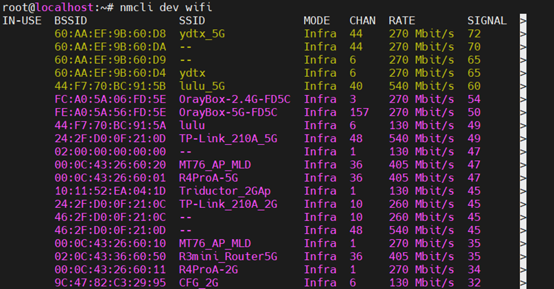
3 使用 nmcli 命令连接扫描到的 WIFI
-
wifi_name 换成需要连接的 WIFI 热点的名字
-
wifi_passwd 换成需要连接的 WIFI 热点的密码
armsom@armsom:~$ sudo nmcli dev wifi connect "wifi_name" password "wifi_password"
Device 'wlan0' successfully activated with '31dbde81-1528-4d2b-839b-422cf88cb7d4'.4 通过 ip addr show wlan0 命令可以查看 wifi 的 IP 地址
armsom@armsom:~$ ip addr show wlan0
4: wlan0: <BROADCAST,MULTICAST,UP,LOWER_UP> mtu 1500 qdisc mq state UP group default qlen 1000
    link/ether 0c:cd:d0:e0:96:d3 brd ff:ff:ff:ff:ff:ff
    inet 192.168.1.205/24 brd 192.168.1.255 scope global dynamic noprefixroute wlan0
       valid_lft 43029sec preferred_lft 43029sec
    inet6 fd45:d3b4:e549::468/128 scope global dynamic noprefixroute
       valid_lft 43028sec preferred_lft 43028sec
    inet6 fd45:d3b4:e549:0:20df:5d70:a5e:c43c/64 scope global dynamic noprefixroute
       valid_lft 5229sec preferred_lft 2529sec
    inet6 fe80::86c0:175a:be0d:28e1/64 scope link noprefixroute
valid_lft forever preferred_lft forever5 使用 ping 命令可以测试 wifi 网络的连通性,ping 命令可以通过 Ctrl+C 快捷键来中断运行
armsom@armsom:~$ sudo ping -I wlan0 www.baidu.com
PING www.wshifen.com (103.235.46.115) from 192.168.1.205 wlan0: 56(84) bytes of data.
64 bytes from 103.235.46.115 (103.235.46.115): icmp_seq=1 ttl=47 time=193 ms
64 bytes from 103.235.46.115 (103.235.46.115): icmp_seq=4 ttl=47 time=161 ms
64 bytes from 103.235.46.115 (103.235.46.115): icmp_seq=5 ttl=47 time=169 ms
64 bytes from 103.235.46.115 (103.235.46.115): icmp_seq=6 ttl=47 time=162 ms
^C
--- www.wshifen.com ping statistics ---
6 packets transmitted, 4 received, 33.3333% packet loss, time 5047ms
rtt min/avg/max/mdev = 160.909/171.260/193.269/13.133 ms6 使用完wifi,若想要断开连接,可以执行下面命令,其中wifi_name是你连接的wifi名称
armsom@armsom:~$ sudo nmcli con down "ydtx"
Connection 'ydtx' successfully deactivated (D-Bus active path: /org/freedesktop/NetworkManager/ActiveConnection/3)服务器版镜像通过图形化方式连接 WIFI
1 登录 linux 系统,有下面三种方式:
-
如果开发板连接了网线,可以通过 ssh 远程登录 linux 系统
-
如果开发板连接好了调试串口,可以使用串口终端登录 linux 系统(串口软件请使用 MobaXterm,使用 minicom 无法显示图形界面)
-
如果连接了开发板到HDMI显示器,可以通过HDMI显示的终端登录到linux系统
2 在命令行中输入 nmtui 命令打开 wifi 连接的界面
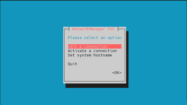
armsom@armsom:~$ sudo nmtui3 选择 Activate a connect 后回车
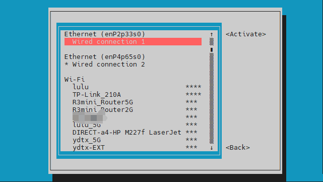
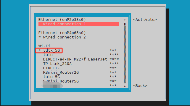
4 选择想要连接的 WIFI 热点,输入密码。WIFI 连接成功后会在已连接的 WIFI 名称前显示一个“*”
5 通过 ip addr show wlan0 命令可以查看 wifi 的 IP 地址
armsom@armsom:~$ ip addr show wlan0
4: wlan0: <BROADCAST,MULTICAST,UP,LOWER_UP> mtu 1500 qdisc mq state UP group default qlen 1000
    link/ether 0c:cd:d0:e0:96:d3 brd ff:ff:ff:ff:ff:ff
    inet 192.168.1.205/24 brd 192.168.1.255 scope global dynamic noprefixroute wlan0
       valid_lft 43029sec preferred_lft 43029sec
    inet6 fd45:d3b4:e549::468/128 scope global dynamic noprefixroute
       valid_lft 43028sec preferred_lft 43028sec
    inet6 fd45:d3b4:e549:0:20df:5d70:a5e:c43c/64 scope global dynamic noprefixroute
       valid_lft 5229sec preferred_lft 2529sec
    inet6 fe80::86c0:175a:be0d:28e1/64 scope link noprefixroute
valid_lft forever preferred_lft forever6 使用 ping 命令可以测试 wifi 网络的连通性,ping 命令可以通过 Ctrl+C 快捷键来中断运行
armsom@armsom:~$ sudo ping -I wlan0 www.baidu.com
PING www.wshifen.com (103.235.46.115) from 192.168.1.205 wlan0: 56(84) bytes of data.
64 bytes from 103.235.46.115 (103.235.46.115): icmp_seq=1 ttl=47 time=193 ms
64 bytes from 103.235.46.115 (103.235.46.115): icmp_seq=4 ttl=47 time=161 ms
64 bytes from 103.235.46.115 (103.235.46.115): icmp_seq=5 ttl=47 time=169 ms
64 bytes from 103.235.46.115 (103.235.46.115): icmp_seq=6 ttl=47 time=162 ms
^C
--- www.wshifen.com ping statistics ---
6 packets transmitted, 4 received, 33.3333% packet loss, time 5047ms
rtt min/avg/max/mdev = 160.909/171.260/193.269/13.133 ms桌面版镜像的测试方法
-
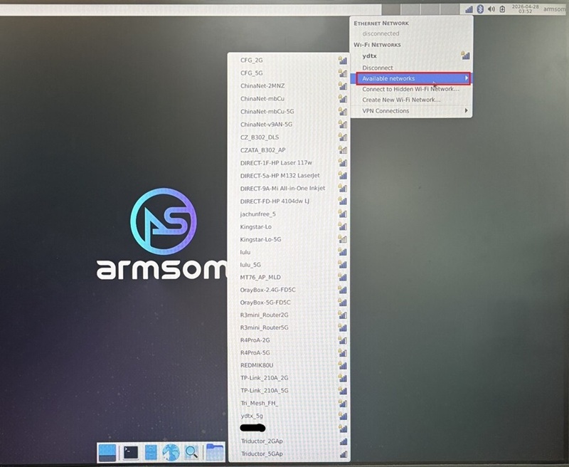
1 点击桌面上右上角的网络配置图标【Select Network】,测试 WIFI 时请不要连接网线。
-
2 连接好 WIFI 后,可以打开浏览器查看是否能上网
¶ BT蓝牙
1 在使用蓝牙功能之前,我们先查看蓝牙的设备节点是否存在,以保证蓝牙初始化正常
armsom@armsom:~$ hciconfig -a
hci0:   Type: Primary  Bus: UART
        BD Address: 0C:CD:D0:E0:96:D4  ACL MTU: 1021:9  SCO MTU: 255:4
        UP RUNNING
        RX bytes:918 acl:0 sco:0 events:71 errors:0
        TX bytes:5480 acl:0 sco:0 commands:71 errors:0
        Features: 0xbf 0xee 0xcd 0xfe 0xd8 0x3f 0x7b 0x87
        Packet type: DM1 DM3 DM5 DH1 DH3 DH5 HV1 HV3
        Link policy: RSWITCH SNIFF
        Link mode: PERIPHERAL ACCEPT
        Name: 'armsom'
        Class: 0x7c0000
        Service Classes: Rendering, Capturing, Object Transfer, Audio, Telephony
        Device Class: Miscellaneous,
        HCI Version: 5.2 (0xb)  Revision: 0x14
        LMP Version: 5.2 (0xb)  Subversion: 0x14
Manufacturer: RivieraWaves S.A.S (96)2 接下来可以使用bluetoothctl进行蓝牙连接
root@localhost:/# bluetoothctl
Agent registered
1. 使能蓝牙控制器
[bluetooth]# power on
Changing power on succeeded
2. 设置控制器为可被发现的
[bluetooth]# discoverable on
Changing discoverable on succeeded
[CHG] Controller 0C:CD:D0:E0:96:D4 Discoverable: yes
3. 设置控制器为可配对的
[bluetooth]# pairable on
Changing pairable on succeeded
4. 开启扫描蓝牙设备
[bluetooth]# scan on
Discovery started
[NEW] Device 53:18:0C:5D:37:D7 53-18-0C-5D-37-D7
[CHG] Device 5E:16:CF:E1:CF:8A RSSI: -79
[NEW] Device 24:2A:EA:61:0F:28 Donleon  #记录下你要连接的设备的MAC地址
[NEW] Device 20:45:30:42:40:8A V9
5. 关闭扫描
[bluetooth]# scan off
Discovery stopped
[CHG] Device 24:2A:EA:61:0F:28 RSSI is nil
[CHG] Controller 0C:CD:D0:E0:96:D4 Discovering: no
6. 将该设备设置为信任设备
[bluetooth]# trust 24:2A:EA:61:0F:28
[CHG] Device 24:2A:EA:61:0F:28 Trusted: yes
Changing 24:2A:EA:61:0F:28 trust succeeded
7. 通过MAC地址与该设备配对
[bluetooth]# pair 24:2A:EA:61:0F:28
Attempting to pair with 24:2A:EA:61:0F:28
[CHG] Device 24:2A:EA:61:0F:28 Connected: yes
Request confirmation
[agent] Confirm passkey 514608 (yes/no): yes     #这里输入yes,同时在手机上也需要确认配对
[CHG] Device 24:2A:EA:61:0F:28 ServicesResolved: yes
[CHG] Device 24:2A:EA:61:0F:28 Paired: yes
Pairing successful    #当此处显示配对成功时,我们再退出(可能需要等待一会)
8. 连接蓝牙设备
[bluetooth]# connect 24:2A:EA:61:0F:28
Attempting to connect to 24:2A:EA:61:0F:28
[CHG] Device 24:2A:EA:61:0F:28 Connected: yes
Connection successful
[CHG] Device 24:2A:EA:61:0F:28 ServicesResolved: yes  #此处显示连接成功即可
9. 查看配对过的设备
[Donleon]# devices
Device 24:2A:EA:61:0F:28 Donleon
10. 查看某个设备的详细信息
[Donleon]# info 24:2A:EA:61:0F:28
11. 移除某个设备
[Donleon]# remove 24:2A:EA:61:0F:28
12. 退出
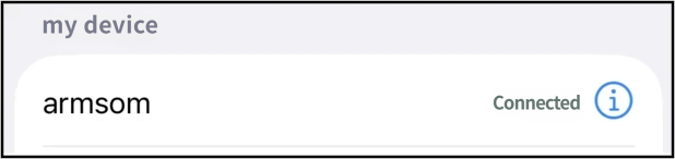
[Donleon]# exit手机上在蓝牙设置里确认与开发板配对:

连接成功后在手机上显示已连接:
¶ HDMI&DP
接 HDMI 或 DP 屏,有两种方式可选:
| 板载接口 | HDMI out | DP out |
|---|---|---|
分辨率 |
8Kp60 |
4Kp60 |
-
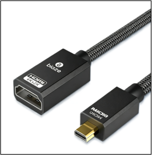
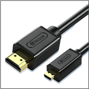
使用 Micro HDMI 线连接sige7s的 HDMI out接口 和 HDMI 显示器:
-
使用一根Micro HDMI 转 HDMI 母线(需要再接一根双HDMI线)
-
-
使用一根Micro HDMI 转 HDMI 公线(可直接接HDMI屏)
2 .使用 Mini DP 线连接sige7s的 DP out接口 和 HDMI 显示器或 DP 显示器 :
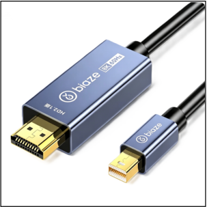
-
使用一根主动式 Mini DP 转 HDMI公线(可直接接HDMI屏)
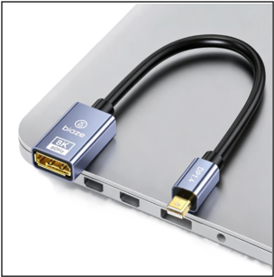
-
使用一根 Mini DP 转 DP 母线(需要再接一根双DP线)
3 .启动 linux 系统后如果显示器有图像输出说明 HDMI 和 DP 接口使用正常
|
很多笔记本电脑虽然带有 HDMI 接口,但是笔记本的 HDMI 接口一般只有输出功能,并没有 HDMI in 的功能,也就是说并不能将其他设备的 HDMI 输出显示到笔记本的屏幕上。 当 HDMI 没有显示的时候,请先检查使用的系统是否是带桌面的版本,如果是服务器版本只能看到终端 Mini DP 转 HDMI 线必需选择主动式,无法使用被动式 |
¶ USB接口
| 型号 | BPI-M7S |
|---|---|
USB接口 |
2x USB3.0, 2x USB2.0 |
| USB 接口是可以接 USB hub 来扩展 USB 接口的数量的。 |
连接 USB 鼠标或键盘测试
-
1.首先将 U 盘或者 USB 移动硬盘插入BPI-M7S 的 USB 接口中
-
2.连接sige7s到 HDMI 或 DP 显示器
-
3.如果鼠标或键盘能正常操作系统说明 USB 接口使用正常(鼠标只有在桌面版的系统中才能使用)
连接 USB 存储设备测试
-
1.首先将 U 盘或者 USB 移动硬盘插入BPI-M7S的 USB 接口中
-
2.执行下面的命令如果能看到 sdX 的输出说明 U 盘识别成功
armsom@armsom:~$ cat /proc/partitions | grep "sd*"
major minor  #blocks  name
   8        0   30720000 sda
8 1 30718976 sda1-
3.使用 mount 命令可以将 U 盘挂载到/mnt 中,然后就能查看 U 盘中的文件了
armsom@armsom:~$ mkdir -p /test
armsom@armsom:~$ sudo mount /dev/sda1 /test/
mount: /test: /dev/sda1 already mounted on /test.-
4.挂载完后通过 df -h 命令就能查看 U 盘的容量使用情况和挂载点
armsom@armsom:/$ df -h | grep "sd"
/dev/sda1 30G 64K 30G 1% /test¶ Micro SD 卡座
BPI-M7S 板载标准的 microSD 卡槽,主要用作系统启动盘或扩展存储空间。
-
当我们使用SD卡用作系统启动盘时,只需在上电前将制作好的SD启动卡插入到 Micro SD card slot,然后再上电, BPI-M7S将优先从SD卡启动。
-
当我们使用SD卡用于拓展存储空间时,可以按如下方式操作,首先查看SD卡插入时日志:
armsom@armsom:~$ [  293.228591] mmc_host mmc1: Bus speed (slot 0) = 148500000Hz (slot req 150000000Hz, actual 148500000HZ div = 0)
[  293.309039] dwmmc_rockchip fe2c0000.mmc: Successfully tuned phase to 155
[  293.309114] mmc1: new ultra high speed SDR104 SDHC card at address 0001
[  293.310505] mmcblk1: mmc1:0001 ASTC 7.44 GiB
[ 293.326321] mmcblk1: p1 p2根据输出信息可以看出,系统已经识别到插入的 SD 卡(mmcblk1,容量7.44 GiB,分区p1和p2),然后我们确认 SD 卡设备信息
armsom@armsom:~$ sudo fdisk -l /dev/mmcblk1
Disk /dev/mmcblk1: 7.44 GiB, 7990149120 bytes, 15605760 sectors
Units: sectors of 1 * 512 = 512 bytes
Sector size (logical/physical): 512 bytes / 512 bytes
I/O size (minimum/optimal): 512 bytes / 512 bytes
Disklabel type: gpt
Disk identifier: BDFDC9CF-2FC3-46BB-AF10-C9DF254BB1E2

Device           Start      End  Sectors  Size Type
/dev/mmcblk1p1   32768  1081343  1048576  512M Linux extended boot
/dev/mmcblk1p2 1081344 15605726 14524383 6.9G Linux filesystem可以看到,文件系统分区为/dev/mmcblk1p2,接着我们按如下方式,挂载我们的 SD 卡
armsom@armsom:~$ sudo mkdir -p /mnt/sdcard
armsom@armsom:~$ sudo mount /dev/mmcblk1p2 /mnt/sdcard
[  491.938107] EXT4-fs (mmcblk1p2): recovery complete
[  491.939897] EXT4-fs (mmcblk1p2): mounted filesystem with ordered data mode. Quota mode: disabled.
mount: (hint) your fstab has been modified, but systemd still uses
       the old version; use 'systemctl daemon-reload' to reload.
armsom@armsom:~$ df -h /mnt/sdcard
Filesystem      Size  Used Avail Use% Mounted on
/dev/mmcblk1p2  6.8G  6.6G     0 100% /mnt/sdcard
armsom@armsom:~$ cd /mnt/sdcard/
armsom@armsom:/mnt/sdcard$ ls
bin   dev  home  lost+found  mnt  proc  run   snap  swapfile  tmp  var
boot etc lib media opt root sbin srv sys usr¶ Audio音频
1 .查看系统中的声卡
armsom@armsom:~$ aplay -l
**** List of PLAYBACK Hardware Devices ****
card 0: rockchipdp0 [rockchip-dp0], device 0: rockchip-dp0 spdif-hifi-0 [rockchip-dp0 spdif-hifi-0]
  Subdevices: 1/1
  Subdevice #0: subdevice #0
card 1: rockchiphdmi0 [rockchip-hdmi0], device 0: rockchip-hdmi0 i2s-hifi-0 [rockchip-hdmi0 i2s-hifi-0]
  Subdevices: 1/1
  Subdevice #0: subdevice #0
card 2: rockchipes8316c [rockchip,es8316-codec], device 0: dailink-multicodecs ES8316 HiFi-0 [dailink-multicodecs ES8316 HiFi-0]
  Subdevices: 1/1
Subdevice #0: subdevice #0列出的声卡信息中, card 2: rockchipes8316c 为板载的 es8316 音频编解码器,用于 3.5mm 耳机接口的输入(麦克风)和输出(音频播放)。
2 .开启音频服务:
在测试录音和播放之前,我们先执行下面命令,自动化配置音频
armsom@armsom:~$ sudo systemctl start es8316-audio-setup3 .录制音频
该功能需要耳机支持麦克风功能,使用 arecord 命令录制音频。
armsom@armsom:~$ arecord -D hw:2,0 -f S16_LE -r 44100 -c 2 -d 5 /tmp/record.wav
Recording WAVE '/tmp/record.wav' : Signed 16 bit Little Endian, Rate 44100 Hz, Stereo4 .播放音频
armsom@armsom:~$ aplay -D hw:2,0 /tmp/record.wav
Playing WAVE '/tmp/record.wav' : Signed 16 bit Little Endian, Rate 44100 Hz, Stereo¶ 40 PIN GPIO
BPI-M7S 提供了一个40pin针脚的GPIO座子,兼容于市面上大部分传感器的应用。
wiring-armbian 的方法
下载 wiringOP 的代码到开发板: https://github.com/ArmSoM/wiring-armbian
下载好 wiringOP 代码后,先编译安装,执行如下命令:
armsom@armsom:/$ cd wiring-armbian/
armsom@armsom:/wiring-armbian$ ./build clean
armsom@armsom:/wiring-armbian$ ./build编译完成后,测试 gpio readall 命令的输出如下
armsom@armsom:/wiring-armbian$ gpio readall
 +------+-----+----------+--------+---+  ArmSoM-Sige7s +---+--------+----------+-----+------+
 | GPIO | wPi |   Name   |  Mode  | V | Physical | V |  Mode  | Name     | wPi | GPIO |
 +------+-----+----------+--------+---+----++----+---+--------+----------+-----+------+
 |      |     |     3.3V |        |   |  1 || 2  |   |        | 5V       |     |      |
 |   29 |   0 | I2C1_SDA |   ALT9 | 1 |  3 || 4  |   |        | 5V       |     |      |
 |   28 |   1 | I2C1_SCL |   ALT9 | 1 |  5 || 6  |   |        | GND      |     |      |
 |   47 |   2 | GPIO1_B7 |   ALT3 | 0 |  7 || 8  | 1 | ALT10  | UART2_TX | 3   | 13   |
 |      |     |      GND |        |   |  9 || 10 | 1 | ALT10  | UART2_RX | 4   | 14   |
 |  128 |   5 | GPIO4_A0 |     IN | 0 | 11 || 12 | 1 | IN     | GPIO1_A7 | 6   | 39   |
 |  129 |   7 | GPIO4_A1 |     IN | 0 | 13 || 14 |   |        | GND      |     |      |
 |  130 |   8 | GPIO4_A2 |     IN | 0 | 15 || 16 | 1 | ALT10  | UART6_TX | 9   | 33   |
 |      |     |     3.3V |        |   | 17 || 18 | 1 | ALT10  | UART6_RX | 10  | 32   |
 |   43 |  11 |  SPI0_TX |     IN | 0 | 19 || 20 |   |        | GND      |     |      |
 |   42 |  12 |  SPI0_RX |     IN | 0 | 21 || 22 | 1 | IN     | GPIO1_B0 | 13  | 40   |
 |   44 |  14 | SPI0_CLK |     IN | 1 | 23 || 24 | 1 | IN     | SPI0_CS0 | 15  | 45   |
 |      |     |      GND |        |   | 25 || 26 | 1 | IN     | SPI0_CS1 | 16  | 46   |
 |  136 |  17 | I2C6_SDA |   ALT9 | 1 | 27 || 28 | 1 | ALT9   | I2C6_SCL | 18  | 137  |
 |  131 |  19 | GPIO4_A3 |     IN | 0 | 29 || 30 |   |        | GND      |     |      |
 |  132 |  20 | GPIO4_A4 |     IN | 0 | 31 || 32 | 1 | ALT11  | PWM2     | 21  | 105  |
 |  133 |  22 | GPIO4_A5 |     IN | 0 | 33 || 34 |   |        | GND      |     |      |
 |  134 |  23 | GPIO4_A6 |     IN | 0 | 35 || 36 | 1 | IN     | GPIO4_B2 | 24  | 138  |
 |  135 |  25 | GPIO4_A7 |     IN | 0 | 37 || 38 | 1 | IN     | GPIO4_B3 | 26  | 139  |
 |      |     |      GND |        |   | 39 || 40 | 1 | IN     | GPIO4_C3 | 27  | 115  |
 +------+-----+----------+--------+---+----++----+---+--------+----------+-----+------+
 | GPIO | wPi |   Name   |  Mode  | V | Physical | V |  Mode  | Name     | wPi | GPIO |
+------+-----+----------+--------+---+ ArmSoM-Sige7s +---+--------+----------+-----+------+设置 GPIO 口为输出模式,其中第三个参数需要输入引脚对应的 wPi 的序号
armsom@armsom:/wiring-armbian$ gpio mode 5 out读取对应引脚当前的电平状态
armsom@armsom:/wiring-armbian$ gpio read 5
0设置 GPIO 口输出高电平,设置完后可以使用万用表测量引脚的电压的数值,如果为 3.3v,说明设置高电平成功
armsom@armsom:/wiring-armbian$ gpio write 5 1
armsom@armsom:/wiring-armbian$ gpio read 5
1设置 GPIO 口输出低电平,设置完后可以使用万用表测量引脚的电压的数值,如果为 0v,说明设置低电平成功
armsom@armsom:/wiring-armbian$ gpio write 5 0
armsom@armsom:/wiring-armbian$ gpio read 5
0其他引脚的设置方法类似,只需修改 wPi 的序号为引脚对应的序号即可
¶ RGB LED
有一个用户(绿灯)和一个电源指示灯(红灯)。
-
用户灯 默认情况下为关闭,可由用户自行操控。
-
电源指示灯 默认情况下,其常亮表示系统运行正常。
用户灯可通过命令控制:
armsom@armsom:~$ echo 1 | sudo tee /sys/class/leds/led2-green-usr/brightness (Light up)
armsom@armsom:~$ echo 0 | sudo tee /sys/class/leds/led2-green-usr/brightness (Close)
armsom@armsom:~$ echo heartbeat | sudo tee /sys/class/leds/led2-green-usr/trigger (Heartbeat light)¶ RTC实时时钟
BPI-M7S板内集成一颗RTC时钟芯片 LK8563.
armsom@armsom:~$ dmesg | grep rtc
[    1.707045] [drm] Cluster1-win0(possible_vp_mask = 0x00000002) has no possible crtcs
[    1.707074] [drm] Cluster1-win1(possible_vp_mask = 0x00000002) has no possible crtcs
[    1.707093] [drm] Cluster3-win0(possible_vp_mask = 0x00000008) has no possible crtcs
[    1.707119] [drm] Cluster3-win1(possible_vp_mask = 0x00000008) has no possible crtcs
[    1.707132] [drm] Esmart1-win0(possible_vp_mask = 0x00000002) has no possible crtcs
[    1.707150] [drm] Esmart3-win0(possible_vp_mask = 0x00000008) has no possible crtcs
[    1.774649] rtc-hym8563 6-0051: rtc information is invalid
[    1.783043] rtc-hym8563 6-0051: registered as rtc0
[ 1.784043] rtc-hym8563 6-0051: setting system clock to 2021-01-01T12:00:00 UTC (1609502400)找到rtc0,然后使用以下命令设置系统时间并同步到rtc0。
//读取RTC芯片当前时间
armsom@armsom:~$ sudo hwclock -r -f /dev/rtc0
2026-04-28 04:10:12.869672+08:00

//查看系统当前时间
armsom@armsom:~$ date
Tue Apr 28 04:11:21 AM CST 2026

//设置系统时间
armsom@armsom:~$ sudo date -s "2026-07-13 10:30:00"
Mon Jul 13 10:30:00 AM CST 2026

//将系统当前时间写入 RTC
armsom@armsom:~$ sudo hwclock -w -f /dev/rtc0

//然后读取 RTC 芯片当前时间
armsom@armsom:~$ sudo hwclock -r -f /dev/rtc0
2026-07-13 10:30:58.518923+08:00关闭RTC电池(关闭电源),10分钟或更长时间后,重新启动BPI-M7S,查看rtc时间
//由于rtc掉电丢失数据,使用hwclock命令查看rtc时钟又回到了之前的初始日期
armsom@armsom:~$ sudo hwclock -r -f /dev/rtc0
2026-04-28 03:50:21.479385+08:00¶ MIPI-CSI摄像头
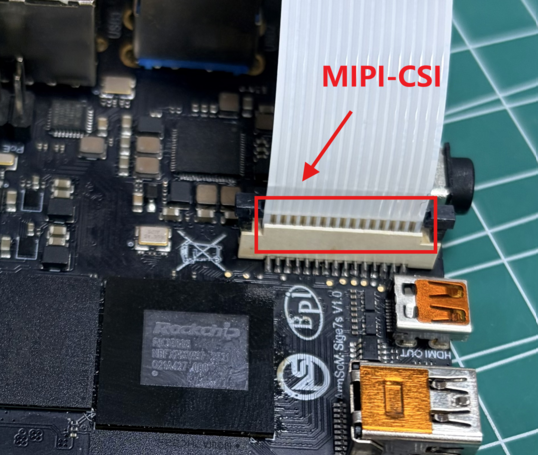
MIPI-CSI接口支持imx219摄像头
-
imx219摄像头接开发板的MIPI-CSI接口,如图所示:
系统默认关闭摄像头功能,若要打开,需要按如下操作打开MIPI-CSI摄像头overlay
root@armsom:~# vi /boot/uEnv/uEnvarmsom-sige7s.txt
找到这部分,将下面这行解除注释即可启用overlay:
#dtoverlay=/dtb/overlay/rk3588-armsom-sige7s-camera-imx219-overlay.dtbo
root@armsom:~# reboot #保存退出后重启打开摄像头配置后,我们先查看驱动是否正常加载
root@armsom:~# dmesg | grep imx219
[    2.045457] platform csi2-dphy0: Fixed dependency cycle(s) with /i2c@feca0000/imx219@10
[    2.333293] imx219 8-0010: module_facing == front
[    2.333306] imx219 8-0010: module_name == GEIR180089
[    2.333316] imx219 8-0010: len_name == LG500627G
[    2.333334] imx219 8-0010: Looking up VANA-supply from device tree
[    2.336240] imx219 8-0010: Looking up VDIG-supply from device tree
[    2.336324] imx219 8-0010: Looking up VDDL-supply from device tree
[    2.345369] imx219 8-0010: imx219_init_controls666
[    2.345391] imx219 8-0010: Consider updating driver imx219 to match on endpoints
[ 2.345406] rockchip-csi2-dphy csi2-dphy0: dphy0 matches m01_f_imx219 8-0010:bus type 5确认驱动加载以后,执行下面命令抓图
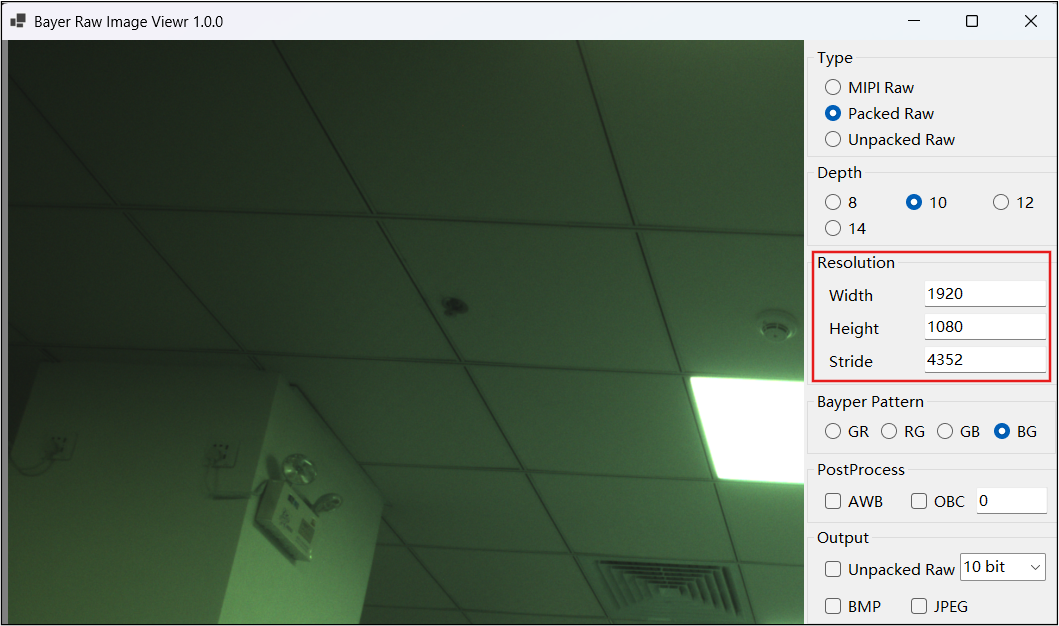
root@armsom:~# v4l2-ctl -d /dev/video0 --set-fmt-video=width=1920,height=1080,pixelformat='BG10' --stream-mmap=3 --stream-skip=4 --stream-to=output.raw --stream-count=1 --stream-poll将抓取的图片 output.raw 使用 Bayer Raw Image Viewer 软件查看,设置参数按如图右侧栏填写即可:
¶ MIPI DSI显示
BPI-M7S MIPI DSI接口适配微雪(兼容树莓派)7寸屏,参考购买链接:
1 .按照下图连接好排线
-
DSI连接器:使用15路扁平柔性线缆(FFC)连接①屏幕FFC连接器和② BPI-M7S MIPI DSI
-
GPIO排针: 使用GPIO电源线连接屏幕③5V&GND接口处和④sige7s 40pin中5V&GND引脚,如pin4和pin6(如果这里pin6被使用,那么串口GND引脚需要接其他GND引脚)
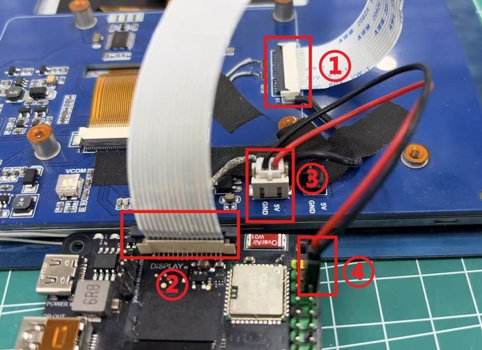
2 .系统默认关闭MIPI-DSI屏幕,若要打开,需要按如下操作打开LCD显示屏overlay
armsom@armsom:~$ sudo vi /boot/uEnv/uEnvarmsom-sige7s.txt
#找到这部分,将下面这行解除注释即可启用overlay:
#dtoverlay=/dtb/overlay/rk3588-armsom-sige7s-display-800x480-7hd-overlay.dtbo
armsom@armsom:~$ sudo reboot #保存退出后重启overlay生效后,观察LCD屏幕是否显示并进入桌面
¶ CPU/GPU/NPU/DDR
以下为BPI-M7S 的CPU GPU NPU DDR定频和性能模式设置方法
定频
CPU 定频
BPI-M7S 的cpu是4个A55+4个A76,分为3组单独管理,节点分别是:
armsom@armsom:~$ ls /sys/devices/system/cpu/cpufreq/policy0  (Corresponding to 4 A55:CPU0-3)
affected_cpus               related_cpus                   scaling_max_freq
cpuinfo_cur_freq            scaling_available_frequencies  scaling_min_freq
cpuinfo_max_freq            scaling_available_governors    scaling_setspeed
cpuinfo_min_freq            scaling_cur_freq               stats
cpuinfo_transition_latency  scaling_driver
ondemand                    scaling_governor

armsom@armsom:~$ ls /sys/devices/system/cpu/cpufreq/policy4  (Corresponding to 2 A76:CPU4-5)
affected_cpus               related_cpus                   scaling_max_freq
cpuinfo_cur_freq            scaling_available_frequencies  scaling_min_freq
cpuinfo_max_freq            scaling_available_governors    scaling_setspeed
cpuinfo_min_freq            scaling_cur_freq               stats
cpuinfo_transition_latency  scaling_driver
ondemand                    scaling_governor

armsom@armsom:~$ ls /sys/devices/system/cpu/cpufreq/policy6   (Corresponding to 2 A76:CPU6-7)
affected_cpus               related_cpus                   scaling_max_freq
cpuinfo_cur_freq            scaling_available_frequencies  scaling_min_freq
cpuinfo_max_freq            scaling_available_governors    scaling_setspeed
cpuinfo_min_freq            scaling_cur_freq               stats
cpuinfo_transition_latency  scaling_driver
ondemand                    scaling_governor

armsom@armsom:~$ cat /sys/devices/system/cpu/cpufreq/policy6/scaling_available_frequencies # Get the current CPU-supported frequency points
408000 600000 816000 1008000 1200000 1416000 1608000 1800000 2016000 2208000 2256000
armsom@armsom:~$ cat /sys/devices/system/cpu/cpufreq/policy6/scaling_available_governors # Get the CPU's running mode
interactive conservative ondemand userspace powersave performance schedutil
# The default is the on-demand frequency scaling mode: ondemand (if you want to restore it, just set it to this mode)| 以下操作切换为root用户执行 |
设置手动定频:
root@armsom:~# cat /sys/devices/system/cpu/cpufreq/policy6/cpuinfo_cur_freq
600000   //查看当前频率
root@armsom:~# echo userspace > /sys/devices/system/cpu/cpufreq/policy6/scaling_governor  //手动定频模式:userspace
root@armsom:~# echo 1608000 > /sys/devices/system/cpu/cpufreq/policy6/scaling_setspeed  设置频率为1608000
root@armsom:~# cat /sys/devices/system/cpu/cpufreq/policy6/cpuinfo_cur_freq  // 确认是否设置成功
1608000其他两组CPU也是类似的方式进行设置,操作对应的节点即可。
GPU定频
GPU的节点路径
root@armsom:~# ls /sys/class/devfreq/fb000000.gpu
available_frequencies  governor  name              target_freq
available_governors    load      polling_interval  timer
cur_freq               max_freq  power             trans_stat
device                 min_freq  subsystem         uevent
root@armsom:~# cat /sys/class/devfreq/fb000000.gpu/available_frequencies // 获取GPU支持的频点
1000000000 900000000 800000000 700000000 600000000 500000000 400000000 300000000
root@armsom:~# cat /sys/class/devfreq/fb000000.gpu/available_governors // 获取GPU运行的模式
rknpu_ondemand dmc_ondemand userspace powersave performance simple_ondemand默认是通用按需调频模式:simple_ondemand(恢复的话设置为该模式即可)
设置手动定频
root@armsom:~# cat /sys/class/devfreq/fb000000.gpu/cur_freq //查看当前频率
300000000
root@armsom:~# echo userspace > /sys/class/devfreq/fb000000.gpu/governor  // 手动定频模式:userspace
root@armsom:~# echo 600000000 > /sys/class/devfreq/fb000000.gpu/userspace/set_freq  // 设置频率为600000000
root@armsom:~# cat /sys/class/devfreq/fb000000.gpu/cur_freq  // 确认是否设置成功
600000000NPU定频
NPU的节点路径
root@armsom:~# ls /sys/class/devfreq/fdab0000.npu/
available_frequencies  device    max_freq  power        trans_stat
available_governors    governor  min_freq  subsystem    uevent
cur_freq               load      name      target_freq
root@armsom:~# cat /sys/class/devfreq/fdab0000.npu/available_frequencies  // 获取NPU支持的频点
300000000 400000000 500000000 600000000 700000000 800000000 900000000 1000000000
root@armsom:~# cat /sys/class/devfreq/fdab0000.npu/available_governors // 获取NPU运行的模式
rknpu_ondemand dmc_ondemand userspace powersave performance simple_ondemand默认是按需调频模式:rknpu_ondemand(恢复的话设置为该模式即可)
设置手动定频
root@armsom:~# cat /sys/class/devfreq/fdab0000.npu/cur_freq //查看当前npu频率
1000000000
root@armsom:~# echo userspace > /sys/class/devfreq/fdab0000.npu/governor // 手动定频模式:userspace
root@armsom:~# echo 600000000 > /sys/class/devfreq/fdab0000.npu/userspace/set_freq // 设置频率为600000000
root@armsom:~# cat /sys/class/devfreq/fdab0000.npu/cur_freq  // 确认是否设置成功
600000000
root@armsom:~# cat /sys/kernel/debug/rknpu/load // 查看NPU的负载
NPU load: Core0: 0%, Core1: 0%, Core2: 0%,DDR定频
DDR的节点路径
root@armsom:~# ls /sys/class/devfreq/dmc/
available_frequencies  downdifferential  min_freq   system_status  upthreshold
available_governors    governor          name       target_freq
cur_freq               load              power      trans_stat
device                 max_freq          subsystem  uevent
root@armsom:~# cat /sys/class/devfreq/dmc/available_frequencies // 获取DDR支持的频点
528000000 1068000000 1560000000 2112000000
root@armsom:~# cat /sys/class/devfreq/dmc/available_governors // 获取DDR运行的模式
rknpu_ondemand dmc_ondemand userspace powersave performance simple_ondemand默认是按需频模式:dmc_ondemand(恢复的话设置为该模式即可)
设置手动定频
root@armsom:~# cat /sys/class/devfreq/dmc/cur_freq // 查看当前频率
528000000
root@armsom:~# echo userspace > /sys/class/devfreq/dmc/governor // 手动定频模式:userspace
root@armsom:~# echo 1560000000 > /sys/class/devfreq/dmc/userspace/set_freq  // 设置频率为1560000000
root@armsom:~# cat /sys/class/devfreq/dmc/cur_freq   // 确认是否设置成功
1560000000性能模式
root@armsom:~$ echo performance > /sys/devices/system/cpu/cpufreq/policy6/scaling_governor
root@armsom:~$ echo performance > /sys/class/devfreq/fb000000.gpu/governor
root@armsom:~$ echo performance > /sys/class/devfreq/dmc/governor
root@armsom:~$ echo performance > /sys/class/devfreq/fdab0000.npu/governor