¶ 简介
Banana Pi BPI-M7 用户手册介绍 BPI-M7 的基本使用方法和准备工作。
BPI-M7 的型号和硬件版本印在开发板上,收到产品后即可查看。
本文尽可能详细地向您概述产品信息。
| 更多信息: 香蕉派 BPI-M7 |
¶ 准备
¶ 工具准备
-
BPI-M7 主板
-
电源:USB Type-C PD
-
支持 9 V/2 A、12 V/2 A、15 V/2 A
-
-
系统安装介质(任选一种)
-
MicroSD/TF 卡启动
-
一张 Class 10 或更高等级、容量至少为 8 GB 的 MicroSD/TF(SDHC)卡,以及一个读卡器
-
以下高速 TF 卡已经 ArmSoM 团队测试:
-
SanDisk 32 GB TF(MicroSD)卡(推荐开发使用)
-
SanDisk 32 GB TF(MicroSD)行车记录仪/监控摄像机存储卡(推荐长期运行使用)
-
闪迪 TF 8G Class10 microSD
-
闪迪 TF 128G Class10 microSD XC TF 128G 48MB/S:
-
-
-
板载 eMMC 启动
-
一根 USB Type-C 数据线,用于通过 BPI-M7 的 Type-C 接口将镜像写入 eMMC;使用时连接 BPI-M7 与电脑。
-
-
¶ 可选配件
-
USB 键盘和鼠标
-
HDMI 显示器和 HDMI 线缆
-
BPI-M7 具有全尺寸 HDMI 端口,最高支持 8K@60 显示
-
系统通过 HDMI EDID 确定最佳显示分辨率。支持 1080p(或 4K/8K)的显示器和电视会选择相应分辨率;如果不支持 1080p,则选择下一个可用分辨率。
-
-
以太网线
-
BPI-M7 支持 2.5GbE
-
网线用于将 BPI-M7 连接到本地网络和互联网
-
-
摄像头模组
-
BPI-M7 支持摄像头功能
-
推荐使用 IMX415 或 OV13850 模块,可通过 Banana Pi 淘宝店或 AliExpress 购买
-
-
LCD 显示屏
-
BPI-M7 支持 LCD 显示
-
推荐使用 Display 10.1 HD,可通过 Banana Pi 淘宝店或 AliExpress 购买
-
-
音频线
-
适用于 0.8 mm 立式插座
-
-
USB-A 转 USB-C 数据线
¶ 调试接口
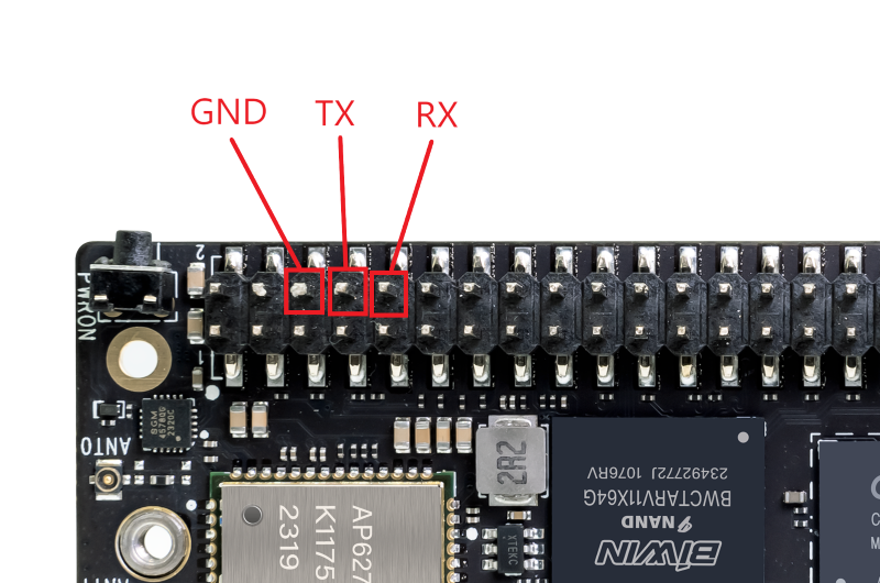
BPI-M7 没有独立的 3 针调试接口;使用 TTL 串口线调试时,需要连接 40 针排针。
连接 40 针排针的第 6、8 和 10 号引脚。
串口波特率为 1500000,请勿选择错误的波特率。
¶ 烧录镜像
| 烧录方法参见:Rockchip 芯片系统镜像烧录 |
¶ 接口设置
首次使用 Banana Pi BPI-M5 Pro 时,请先熟悉各个外设接口,以便理解以下内容。
¶ 调试串口
按照下表连接 USB 转 TTL 串口线,并将波特率设为 1500000:
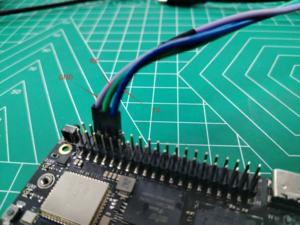
| BPI-M5 Pro | 连接 | 串口模块 |
|---|---|---|
GND(引脚 6) |
←-→ |
GND |
TX(引脚 8) |
←-→ |
RX |
RX(引脚 10) |
←-→ |
TX |
¶ 以太网接口
-
1. 将网线一端插入 ArmSoM-SigeX 的以太网接口,另一端连接到网络正常的路由器。
-
2. 系统启动后会通过 DHCP 自动为以太网接口分配 IP 地址,无需额外配置。
-
3. 使用以下命令查看 ArmSoM-SigeX Linux 系统中的 IP 地址:
armsom@armsom-sige7:~$ ip a
1: lo: <LOOPBACK,UP,LOWER_UP> mtu 65536 qdisc noqueue state UNKNOWN group default qlen 1000
    link/loopback 00:00:00:00:00:00 brd 00:00:00:00:00:00
    inet 127.0.0.1/8 scope host lo
       valid_lft forever preferred_lft forever
    inet6 ::1/128 scope host
       valid_lft forever preferred_lft forever
2: enP4p65s0: <BROADCAST,MULTICAST,UP,LOWER_UP> mtu 1500 qdisc mq state UP group default qlen 1000
    link/ether c6:9c:b0:7e:2b:1f brd ff:ff:ff:ff:ff:ff permaddr aa:a6:84:1b:0d:21
    inet 192.168.10.54/24 brd 192.168.10.255 scope global dynamic noprefixroute enP4p65s0
       valid_lft 86221sec preferred_lft 86221sec
    inet6 fe80::5bb0:d96f:926d:b334/64 scope link noprefixroute
       valid_lft forever preferred_lft forever
3: enP2p33s0: <NO-CARRIER,BROADCAST,MULTICAST,UP> mtu 1500 qdisc mq state DOWN group default qlen 1000
    link/ether be:ed:22:01:47:d9 brd ff:ff:ff:ff:ff:ff permaddr a2:fb:fa:79:de:fb
4: wlan0: <NO-CARRIER,BROADCAST,MULTICAST,UP,LOWER_UP> mtu 1500 qdisc pfifo_fast state DORMANT group default qlen 1000
link/ether b8:2d:28:5a:52:6a brd ff:ff:ff:ff:ff:ffRockchip 产品启动后,可通过以下三种方式查看 IP 地址:
-
连接 HDMI 显示器并登录系统,在终端中输入 ip a 查看 IP 地址。
-
使用调试串口终端登录,输入 ip a 查看 IP 地址。
-
如果没有调试串口或 HDMI 显示器,可通过路由器管理界面查看 ArmSoM-SigeX 以太网接口的 IP 地址。但路由器有时可能不显示该地址;遇到这种情况时,请按以下步骤排查:
-
确认 Linux 系统已正常启动。ArmSoM-SigeX 的绿灯常亮时通常表示启动正常;如果只有红灯亮,则系统未正常启动。
-
检查网线是否连接牢固,或更换一根网线。 尝试使用不同的路由器。路由器的常见问题包括无法分配 IP 地址或正确分配 IP 地址但未在路由器界面中显示它们。
-
如果没有其他路由器可用,请使用 HDMI 显示器或调试串口查看 IP 地址。
-
| Rockchip 产品通过 DHCP 自动获取 IP 地址,无需额外配置。 |
-
4. 使用 ping 工具检查网络连通性。
-
测试命令如下;按 Ctrl+C 可停止 ping。
-
armsom@armsom-sige7:~$ ping www.baidu.com
PING www.a.shifen.com (183.2.172.185): 56 data bytes
64 bytes from 183.2.172.185: icmp_seq=0 ttl=53 time=8.370 ms
64 bytes from 183.2.172.185: icmp_seq=1 ttl=53 time=8.917 ms
64 bytes from 183.2.172.185: icmp_seq=2 ttl=53 time=8.511 ms
64 bytes from 183.2.172.185: icmp_seq=3 ttl=53 time=8.673 ms
^C
--- www.a.shifen.com ping statistics ---
4 packets transmitted, 4 packets received, 0% packet loss
round-trip min/avg/max/stddev = 8.370/8.618/8.917/0.203 ms¶ WiFi
Banana Pi 采用 Rockchip 平台的产品配有板载 WiFi 模块,无需外接无线网卡,并使用标准第四代天线。
¶ 在服务器版镜像中通过命令行连接 WiFi
-
首先登录 Linux 系统,可使用以下方式之一:
-
开发板已连接网线时,可通过 SSH 远程登录。
-
开发板已连接调试串口时,可通过串口终端登录 Linux 系统。
-
开发板已连接 HDMI 显示器时,可使用屏幕上显示的终端登录 Linux 系统。
-
-
使用 nmcli dev wifi 命令扫描可用的 WiFi 热点:
# 1. Enable WIFI
armsom@armsom-sige:/# nmcli r wifi on
# 2. Scan for WIFI
armsom@armsom-sige:/# nmcli dev wifi
# 3. Connect to a WIFI network
armsom@armsom-sige:/# nmcli dev wifi connect "wifi_name" password "wifi_password"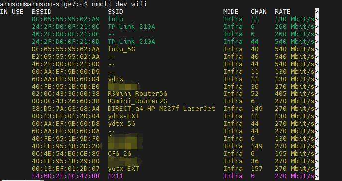
-
使用 nmcli 命令连接扫描到的 WiFi 网络:
-
将 wifi_name 替换为要连接的 WiFi 热点名称。
-
将 wifi_password 替换为该热点的密码。
-
armsom@armsom-sige7:~$ nmcli dev wifi connect "ydtx_5G" password "ydtx123456"
Device 'wlan0' successfully activated with "wlan0b6d10bba-e1d5-4b6d-a17f-7d5ab44bbb6f".-
使用 ip addr show wlan0 命令查看 WiFi 连接的 IP 地址:
armsom@armsom-sige7:~$ ip addr show wlan0
4: wlan0: <BROADCAST,MULTICAST,UP,LOWER_UP> mtu 1500 qdisc pfifo_fast state UP group default qlen 1000
    link/ether b8:2d:28:5a:52:6a brd ff:ff:ff:ff:ff:ff
    inet 192.168.10.9/24 brd 192.168.10.255 scope global dynamic noprefixroute wlan0
       valid_lft 86321sec preferred_lft 86321sec
    inet6 fe80::850d:3119:e0:afa3/64 scope link noprefixroute
valid_lft forever preferred_lft forever-
使用 ping 命令测试 WiFi 网络连通性;按 Ctrl+C 可停止测试:
armsom@armsom-sige7:~$ ping www.baidu.com
PING www.a.shifen.com (183.2.172.185): 56 data bytes
64 bytes from 183.2.172.185: icmp_seq=0 ttl=53 time=8.370 ms
64 bytes from 183.2.172.185: icmp_seq=1 ttl=53 time=8.917 ms
64 bytes from 183.2.172.185: icmp_seq=2 ttl=53 time=8.511 ms
64 bytes from 183.2.172.185: icmp_seq=3 ttl=53 time=8.673 ms
^C
--- www.a.shifen.com ping statistics ---
4 packets transmitted, 4 packets received, 0% packet loss
round-trip min/avg/max/stddev = 8.370/8.618/8.917/0.203 ms¶ 在服务器版镜像中通过图形界面连接 WiFi
-
登录 Linux 系统,可使用以下方式之一:
-
开发板已连接网线时,可通过 SSH 远程登录。
-
开发板已连接调试串口时,可通过串口终端登录 Linux 系统;请使用 MobaXterm,因为 Minicom 无法显示图形界面。
-
开发板已连接 HDMI 显示器时,可使用屏幕上显示的终端登录 Linux 系统。
-
-
在终端输入 nmtui,打开 WiFi 连接界面:
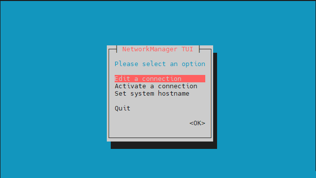
armsom@armsom-sige7:~$ nmtui-
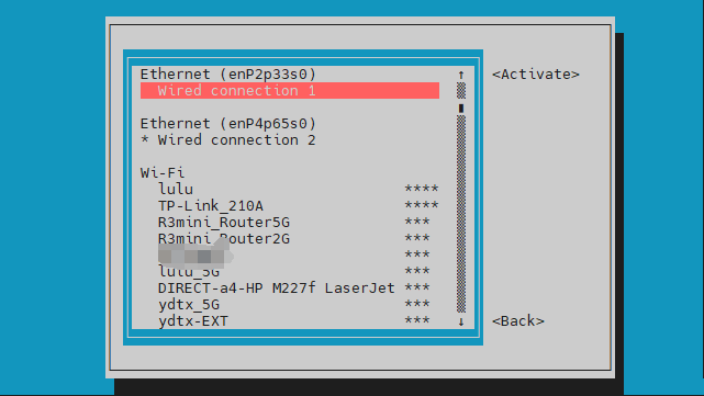
选择“Activate a connection”,然后按 Enter 键:
-
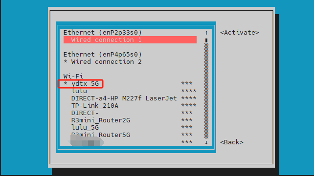
选择要连接的 WiFi 热点并输入密码。连接成功后,该网络名称旁会显示星号“*”:
-
使用 ip addr show wlan0 命令查看 WiFi 连接的 IP 地址:
armsom@armsom-sige7:~$ ip addr show wlan0
4: wlan0: <BROADCAST,MULTICAST,UP,LOWER_UP> mtu 1500 qdisc pfifo_fast state UP group default qlen 1000
    link/ether b8:2d:28:5a:52:6a brd ff:ff:ff:ff:ff:ff
    inet 192.168.10.9/24 brd 192.168.10.255 scope global dynamic noprefixroute wlan0
       valid_lft 86316sec preferred_lft 86316sec
    inet6 fe80::a422:3494:3147:92d/64 scope link noprefixroute
valid_lft forever preferred_lft forever-
使用 ping 命令测试 WiFi 网络连通性;按 Ctrl+C 可停止测试:
armsom@armsom-sige7:~$ ping www.baidu.com
PING www.a.shifen.com (183.2.172.185): 56 data bytes
64 bytes from 183.2.172.185: icmp_seq=0 ttl=53 time=8.370 ms
64 bytes from 183.2.172.185: icmp_seq=1 ttl=53 time=8.917 ms
64 bytes from 183.2.172.185: icmp_seq=2 ttl=53 time=8.511 ms
64 bytes from 183.2.172.185: icmp_seq=3 ttl=53 time=8.673 ms
^C
--- www.a.shifen.com ping statistics ---
4 packets transmitted, 4 packets received, 0% packet loss
round-trip min/avg/max/stddev = 8.370/8.618/8.917/0.203 ms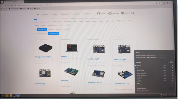
¶ BT
# 1. Activate Bluetooth
armsom@armsom-sige5:/# service bluetooth start
# 2. Enter bluetoothctl
armsom@armsom-sige5:/# bluetoothctl
# 3. Enter the following command to connect
armsom@armsom-sige5:/# power on
armsom@armsom-sige5:/# agent on
armsom@armsom-sige5:/# default-agent
armsom@armsom-sige5:/# scan on
armsom@armsom-sige5:/# pair yourDeviceMAC¶ HDMI
BPI-M5 Pro 配有一个 HDMI 输出接口,支持 CEC 和 HDMI 2.1,最高分辨率为 4Kp120。
| 型号 | BPI-M7 | BPI-M5 Pro | BPI-M1 Pro |
|---|---|---|---|
分辨率 |
8Kp60 |
4Kp120 |
4Kp60 |
使用 HDMI 线缆将开发板连接到 HDMI 显示器。
Linux 系统启动后,如果 HDMI 显示器能正常显示画面,则 HDMI 接口工作正常。
| 许多笔记本电脑虽有 HDMI 接口,但通常只支持输出,不支持 HDMI 输入,因此不能直接显示开发板输出的画面。连接前请确认笔记本电脑支持 HDMI 输入。如果没有画面,还应确认使用的是桌面版系统;服务器版可能只显示终端。 |
-
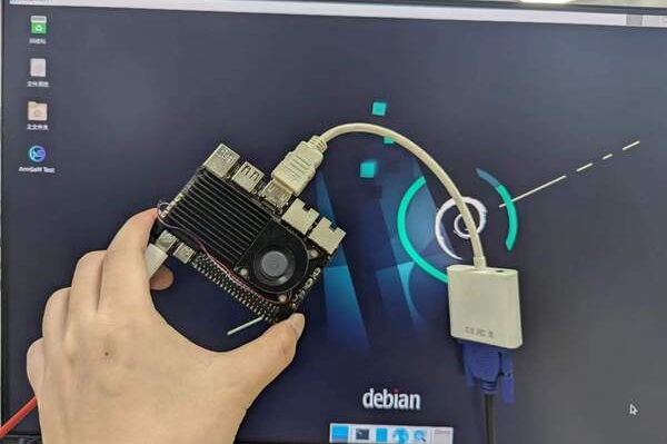
1. HDMI 转 VGA 显示测试
-
所需配件:
-
HDMI 转 VGA 转换器
-
-
2. 一条 VGA 线和一台带 VGA 接口的显示器
HDMI 转 VGA 显示测试如下图所示:
| 使用 HDMI 转 VGA 时,无需在 ArmSoM-Sige 产品或 Linux 系统中进行额外配置。如遇问题,请检查 HDMI 转 VGA 转换器、VGA 线和显示器。 |
¶ USB
BPI-M5 Pro 提供一个 USB 2.0 接口和一个 USB 3.0 接口。
| 型号 | BPI-M7 | BPI-M5 Pro | BPI-M1 Super |
|---|---|---|---|
USB |
1 × Type-C 3.0、1 × USB 3.0、1 × USB 2.0 |
1 × Type-C 3.0、1 × USB 3.0、1 × USB 2.0 |
2 × USB 2.0 |
| 可使用 USB 集线器扩展 USB 接口。 |
¶ 测试 USB 鼠标或键盘
-
1. 将 USB 键盘或鼠标插入开发板的 USB 接口。
-
2. 将开发板连接到 HDMI 显示器。
-
3. 如果键盘或鼠标能正常操作系统,则 USB 接口工作正常(鼠标仅适用于桌面版系统)。
¶ 测试 USB 存储设备
-
1. 将 U 盘或 USB 移动硬盘插入 ArmSoM-Sige 产品的 USB 接口。
-
2. 运行以下命令;如果输出中出现 sdX 设备,则表示 USB 存储设备已被识别:
armsom@armsom-sige7:/# cat /proc/partitions | grep "sd*"
major minor  #blocks  name
8 0 122880000 sda-
3. 使用 mount 命令将 USB 存储设备挂载到 /mnt,然后即可查看其中的文件:
armsom@armsom-sige7:/# sudo mount /dev/sda1 /test/-
4. 挂载后,使用 df -h 命令查看设备容量使用情况和挂载点:
armsom@armsom-sige7:/test# df -h | grep "sd"
/dev/sda 4.7G 4.7G 0 100% /test¶ USB 摄像头
-
1. 准备一个支持 UVC 协议的 USB 摄像头,并将其连接到开发板的 USB 接口。
-
2. 使用 v4l2-ctl 命令查看 USB 摄像头的设备节点信息,通常为 /dev/video0:
armsom@armsom-sige7:/# v4l2-ctl --list-devices
Logitech HD Webcam C93 (usb-xhci-hcd.5.auto-1):
        /dev/video40
        /dev/video41
/dev/media4-
3. 在桌面版系统中,可使用 Cheese/V4L2 Test Bench 直接打开 USB 摄像头。
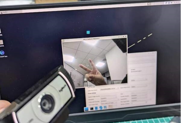
也可使用终端命令预览摄像头:
armsom@armsom-sige7:/# gst-launch-1.0 v4l2src device=/dev/video0 io-mode=4 ! videoconvert ! video/x-raw,format=NV12,width=1920,height=1080 ! xvimagesink;要拍摄照片:
armsom@armsom-sige7:/# gst-launch-1.0 v4l2src device=/dev/video0 io-mode=4 ! videoconvert ! video/x-raw,format=NV12,width=1920,height=1080 ! jpegenc ! multifilesink location=/home/armsom/test.jpg;录制视频:
gst-launch-1.0 v4l2src num-buffers=512 device=/dev/video0 io-mode=4 ! videoconvert ! video/x-raw, format=NV12, width=1920, height=1080, framerate=30/1 ! tee name=t ! queue ! mpph264enc ! queue ! h264parse ! mpegtsmux ! filesink location=/home/armsom/test.mp4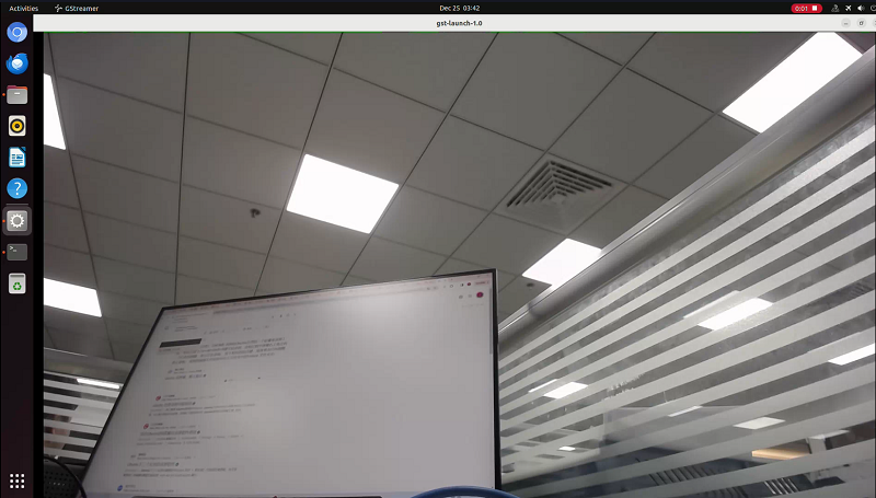
¶ 音频
查看系统中的声卡:
armsom@armsom-sige5:/# aplay -l
**** List of PLAYBACK Hardware Devices ****
card 0: rockchipdp0 [rockchip,dp0], device 0: rockchip,dp0 spdif-hifi-0 [rockchip,dp0 spdif-hifi-0]
 Subdevices: 1/1
 Subdevice #0: subdevice #0
card 1: rockchipes8316 [rockchip-es8316], device 0: fe470000.i2s-ES8316 HiFi es8316.7-0011-0 [fe470000.i2s-ES8316 HiFi es8316.7-0011-0]
  Subdevices: 1/1
  Subdevice #0: subdevice #0
card 2: rockchiphdmi0 [rockchip-hdmi0], device 0: rockchip-hdmi0 i2s-hifi-0 [rockchip-hdmi0 i2s-hifi-0]
  Subdevices: 1/1
Subdevice #0: subdevice #0¶ 风扇
BPI-M5 Pro 产品支持使用 0.8 mm 连接器的 5 V 风扇。
风扇默认具有以下五档状态:
| 温度范围 | 状态 | PWM 速度 |
|---|---|---|
低于 50 °C |
0 |
0 |
50°C - 55°C |
1 |
50 |
55°C - 60°C |
2 |
100 |
60°C - 65°C |
3 |
150 |
65°C - 70°C |
4 |
200 |
高于 70 °C |
5 |
250 |
armsom@armsom-sige5:/# echo 100 > /sys/devices/platform/pwm-fan/hwmon/hwmon6/pwm1¶ USB Type-C
BPI-M5 Pro 配备全功能 USB Type-C 3.0 接口,支持最高 8K@30fps 的 DP 显示输出。
¶ 40 针 GPIO
BPI-M5 Pro/BPI-M7 提供一个 40 针 GPIO 排针,可兼容市面上的大多数传感器。
¶ wiring-armbian 使用说明
从 wiring-armbian 下载 wiringOP 代码:https://github.com/ArmSoM/wiring-armbian
-
使用 gpio readall 命令查看引脚状态,输出如下图所示:
+------+-----+----------+--------+---+  ArmSoM-Sige7(BPI-M7) +---+--------+----------+-----+------+
| GPIO | wPi |   Name   |  Mode  | V | Physical | V |  Mode  | Name     | wPi | GPIO |
+------+-----+----------+--------+---+----++----+---+--------+----------+-----+------+
|      |     |     3.3V |        |   |  1 || 2  |   |        | 5V       |     |      |
|  139 |   0 |    SDA.7 |     IN | 1 |  3 || 4  |   |        | 5V       |     |      |
|  138 |   1 |    SCL.7 |     IN | 1 |  5 || 6  |   |        | GND      |     |      |
|  115 |   2 |    PWM15 |    OUT | 0 |  7 || 8  | 1 | ALT10  | GPIO0_B5 | 3   | 13   |
|      |     |      GND |        |   |  9 || 10 | 1 | ALT10  | GPIO0_B6 | 4   | 14   |
|  113 |   5 | GPIO3_C1 |     IN | 0 | 11 || 12 | 1 | IN     | GPIO3_B5 | 6   | 109  |
|  111 |   7 | GPIO3_B7 |     IN | 0 | 13 || 14 |   |        | GND      |     |      |
|  112 |   8 | GPIO3_C0 |     IN | 0 | 15 || 16 | 0 | IN     | GPIO3_A4 | 9   | 100  |
|      |     |     3.3V |        |   | 17 || 18 | 1 | IN     | GPIO4_C4 | 10  | 148  |
|   42 |  11 | SPI0_TXD |     IN | 1 | 19 || 20 |   |        | GND      |     |      |
|   41 |  12 | SPI0_RXD |     IN | 1 | 21 || 22 |   |        | SARADC_IN4 |     |      |
|   43 |  14 | SPI0_CLK |     IN | 1 | 23 || 24 | 1 | IN     | SPI0_CS0 | 15  | 44   |
|      |     |      GND |        |   | 25 || 26 | 1 | IN     | SPI0_CS1 | 16  | 45   |
|  150 |  17 | GPIO4_C6 |     IN | 1 | 27 || 28 | 0 | OUT    | GPIO4_C5 | 18  | 149  |
|   63 |  19 | GPIO1_D7 |     IN | 1 | 29 || 30 |   |        | GND      |     |      |
|   47 |  20 | GPIO1_B7 |     IN | 1 | 31 || 32 | 0 | IN     | GPIO3_C2 | 21  | 114  |
|  103 |  22 | GPIO3_A7 |     IN | 1 | 33 || 34 |   |        | GND      |     |      |
|  110 |  23 | GPIO3_B6 |     IN | 0 | 35 || 36 | 0 | IN     | GPIO3_B1 | 24  | 105  |
|    0 |  25 | GPIO0_A0 |     IN | 1 | 37 || 38 | 0 | IN     | GPIO3_B2 | 26  | 106  |
|      |     |      GND |        |   | 39 || 40 | 1 | IN     | GPIO3_B3 | 27  | 107  |
+------+-----+----------+--------+---+----++----+---+--------+----------+-----+------+
| GPIO | wPi |   Name   |  Mode  | V | Physical | V |  Mode  | Name     | wPi | GPIO |
+------+-----+----------+--------+---+  ArmSoM-Sige7(BPI-M7) +---+--------+----------+-----+------+
-
将 GPIO 引脚设为输出模式。第三个参数应填写该引脚对应的 wPi 编号。
root@armsom-sige7:~/wiring-armbian# gpio mode 2 out-
设置 GPIO 引脚输出低电平。设置完毕后,可以用万用表测量该引脚上的电压;如果读数为0V,则低电平设置成功。
root@armsom-sige7:~/wiring-armbian# gpio write 2 0-
设置 GPIO 引脚输出高电平。设置完毕后,可以用万用表测量该引脚上的电压;如果读取到3.3V,则高电平设置成功。
root@armsom-sige7:~/wiring-armbian# gpio write 2 1-
其他引脚的设置方法相同,只需将 wPi 编号改为对应引脚的编号。
¶ RGB LED
BPI-M5 Pro 配有绿色和红色两个用户 LED。
-
绿色用户 LED 默认常亮,表示内核正在运行。
-
红色用户 LED 默认熄灭,可由用户控制。
用户可以通过命令进行控制:
armsom@armsom-sige5:/# sudo su
armsom@armsom-sige5:/# echo timer > /sys/class/leds/red/trigger
armsom@armsom-sige5:/# echo activity > /sys/class/leds/red/trigger¶ 实时时钟
-
BPI-M5 Pro 配备 LK8563S RTC 芯片。
-
首先通过 2 针 0.8 mm 接口连接 RTC 电池,为 RTC 芯片供电。
| RTC 电池应保持连接,并确认系统已经创建 LK8563S RTC 设备。 |
armsom@armsom-sige5:/# dmesg | grep rtc
[ 6.407133] rtc-hym8563 6-0051: rtc information is valid
[ 6.412731] rtc-hym8563 6-0051: registered as rtc0
[ 6.413779] rtc-hym8563 6-0051: setting system clock to 2022-06-22T01:22:26 UTC (1655860946)-
找到 rtc0 后,使用以下命令设置系统时间并同步到 rtc0:
armsom@armsom-sige5:/# hwclock -r
2023-11-03 10:32:40.461910+00:00
armsom@armsom-sige5:/# date
Fri 3rd Nov 10:33:12 UTC 2023
armsom@armsom-sige5:/# hwclock -w
armsom@armsom-sige5:/# hwclock -r
armsom@armsom-sige5:/# poweroff-
取出 RTC 电池,等待至少 10 分钟后重新装入并启动 Sige5,检查 RTC 时间是否与系统时钟同步:
armsom@armsom-sige5:/# hwclock -r
2023-11-03 10:35:40.461910+00:00
armsom@armsom-sige5:/# date
Fri 3rd Nov 10:36:01 UTC 2023¶ M.2 接口
BPI-M5 Pro 提供 M.2 连接器:
产品背面有一个单通道 PCIe 2.0 的 M.2 M Key 连接器,并设有标准 2280 安装孔,可安装 M.2 2280 NVMe SSD。
| 此 M.2 接口不支持 M.2 SATA SSD。 |
armsom@armsom-sige5:/# mkdir temp
armsom@armsom-sige5:/# mount /dev/nvme0n1 temp¶ MIPI-CSI
¶ IMX415
摄像头采用 IMX415 模块。连接摄像头模块并上电后,可查看启动日志:
armsom@armsom-sige5:/# dmesg | grep imx415
[    2.547754] imx415 3-001a: driver version: 00.01.08
[    2.547767] imx415 3-001a:  Get hdr mode failed! no hdr default
[    2.547819] imx415 3-001a: Failed to get power-gpios
[    2.547826] imx415 3-001a: could not get default pinstate
[    2.547831] imx415 3-001a: could not get sleep pinstate
[    2.547850] imx415 3-001a: supply dvdd not found, using dummy regulator
[    2.547918] imx415 3-001a: supply dovdd not found, using dummy regulator
[    2.547945] imx415 3-001a: supply avdd not found, using dummy regulator
[    2.613843] imx415 3-001a: Detected imx415 id 0000e0
[    2.613890] rockchip-csi2-dphy csi2-dphy0: dphy0 matches m00_b_imx415 3-001a:bus type 5
[   18.386174] imx415 3-001a: set fmt: cur_mode: 3864x2192, hdr: 0
[ 18.389067] imx415 3-001a: set exposure(shr0) 2047 = cur_vts(2250) - val(203)使用 v4l2-ctl 进行图像捕获:
/ MIPI-CSI1
armsom@armsom-sige5:/# v4l2-ctl -d /dev/video31 --set-fmt-video=width=3840,height=2160,pixelformat=NV12 --stream-mmap=3 --stream-skip=60 --stream-to=/tmp/cif73.out --stream-count=3 --stream-poll

// MIPI-CSI2
armsom@armsom-sige5:/# v4l2-ctl -d /dev/video22 --set-fmt-video=width=3840,height=2160,pixelformat=NV12 --stream-mmap=3 --stream-skip=60 --stream-to=/tmp/cif73.out --stream-count=3 --stream-poll使用 gst-launch-1.0 直接显示视频:
// MIPI-CSI1
armsom@armsom-sige5:/# gst-launch-1.0 v4l2src device=/dev/video31 ! video/x-raw,format=NV12,width=3840,height=2160, framerate=30/1 ! xvimagesink

// MIPI-CSI2
armsom@armsom-sige5:/# gst-launch-1.0 v4l2src device=/dev/video22 ! video/x-raw,format=NV12,width=3840,height=2160, framerate=30/1 ! xvimagesink¶ ov13850
此模块的使用方法与 IMX415 类似,具体如下:
摄像头采用 OV13850。连接摄像头模块并上电后,可查看启动日志。
root@armsom-sige7:/# dmesg | grep ov13850
[    2.302905] ov13850 5-0010: driver version: 00.01.05
[    2.302944] ov13850 5-0010: Failed to get power-gpios, maybe no use
[    2.303067] ov13850 5-0010: supply avdd not found, using dummy regulator
[    2.303153] ov13850 5-0010: supply dovdd not found, using dummy regulator
[    2.303186] ov13850 5-0010: supply dvdd not found, using dummy regulator
[    2.303213] ov13850 5-0010: could not get default pinstate
[    2.303220] ov13850 5-0010: could not get sleep pinstate
[    2.308532] ov13850 5-0010: Detected OV00d850 sensor, REVISION 0xb2
[    2.332058] ov13850 5-0010: Consider updating driver ov13850 to match on endpoints
[ 2.332084] rockchip-csi2-dphy csi2-dphy0: dphy0 matches m00_b_ov13850 5-0010:bus type 5使用 v4l2-ctl 进行图像捕获:
// MIPI-CSI1
root@armsom-sige7:/# v4l2-ctl -d /dev/video31 --set-selection=target=crop,top=0,left=0,width=2112,height=1568 --set-fmt-video=width=2112,height=1568,pixelformat=NV12 --stream-mmap=3 --stream-to=/nv12.bin --stream-count=1 --stream-poll

// MIPI-CSI2
root@armsom-sige7:/# v4l2-ctl -d /dev/video22 --set-selection=target=crop,top=0,left=0,width=2112,height=1568 --set-fmt-video=width=2112,height=1568,pixelformat=NV12 --stream-mmap=3 --stream-to=/nv12.bin --stream-count=1 --stream-poll使用 gst-launch-1.0 显示视频
// MIPI-CSI1
root@armsom-sige7:/# gst-launch-1.0 v4l2src device=/dev/video31 ! video/x-raw,format=NV12,width=2112,height=1568, framerate=30/1 ! xvimagesink

// MIPI-CSI2
root@armsom-sige7:/# gst-launch-1.0 v4l2src device=/dev/video22 ! video/x-raw,format=NV12,width=2112,height=1568, framerate=30/1 ! xvimagesink
root@armsom-sige7:/# gst-launch-1.0 v4l2src device=/dev/video0 ! video/x-raw,format=NV12,width=2112,height=1568, framerate=30/1 ! xvimagesink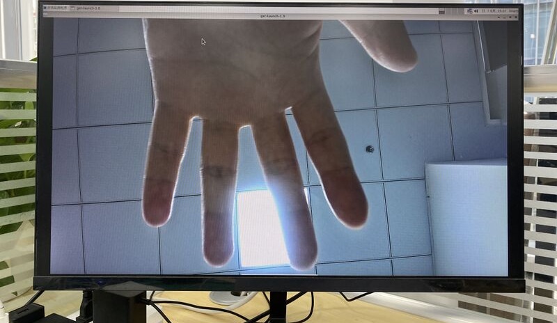
¶ MIPI DSI
BPI-M7 的 MIPI DSI 最高支持 4K@120Hz 分辨率。
-
1. 按照下图连接排线。
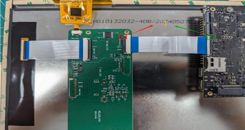
-
2. 配置 10.1 英寸 MIPI LCD 屏幕
-
Linux 镜像默认未启用 MIPI LCD 屏幕配置,使用前需要手动启用。
-
使用 nano 打开 /boot/armbianEnv.txt 文件:
-
sudo nano /boot/armbianEnv.txt-
在文件中查找或添加“overlays=”配置项。
// Choose according to your product
overlays=armsom-sige7-display-10hd // Sige7
overlays=armsom-sige5-display-10hd // Sige5
overlays=armsom-sige3-display-10hd // Sige3快捷键:按 Ctrl+S 保存,按 Ctrl+X 退出。
编辑完成后重启设备,使 Display 10 HD 的 Overlay 设置生效。
¶ CPU/GPU/NPU/DDR
以下以 BPI-M7 为例,说明如何设置 CPU、GPU、NPU 和 DDR 的固定频率及性能模式。
¶ 固定频率设置
¶ CPU 固定频率
BPI-M7 的 CPU 由四个 A55 核心和四个 A76 核心组成,分为三个独立组管理,对应节点如下:
/sys/devices/system/cpu/cpufreq/policy0: (corresponding to 4 A55: CPU0-3)
affected_cpus     cpuinfo_max_freq  cpuinfo_transition_latency  scaling_available_frequencies  scaling_cur_freq  scaling_governor  scaling_min_freq  stats
cpuinfo_cur_freq  cpuinfo_min_freq  related_cpus                scaling_available_governors    scaling_driver    scaling_max_freq  scaling_setspeed

/sys/devices/system/cpu/cpufreq/policy4: (corresponding to 2 A76: CPU4-5)
affected_cpus     cpuinfo_max_freq  cpuinfo_transition_latency  scaling_available_frequencies  scaling_cur_freq  scaling_governor  scaling_min_freq  stats
cpuinfo_cur_freq  cpuinfo_min_freq  related_cpus                scaling_available_governors    scaling_driver    scaling_max_freq  scaling_setspeed

/sys/devices/system/cpu/cpufreq/policy6: (corresponding to 2 A76: CPU6-7)
affected_cpus     cpuinfo_max_freq  cpuinfo_transition_latency  scaling_available_frequencies  scaling_cur_freq  scaling_governor  scaling_min_freq  stats
cpuinfo_cur_freq  cpuinfo_min_freq  related_cpus                scaling_available_governors    scaling_driver    scaling_max_freq  scaling_setspeed

root@armsom-sige7:/ # cat /sys/devices/system/cpu/cpufreq/policy6/scaling_available_frequencies // Get current supported CPU frequencies
408000 600000 816000 1008000 1200000 1416000 1608000 1800000 2016000 2208000 2400000
root@armsom-sige7:/ # cat /sys/devices/system/cpu/cpufreq/policy6/scaling_available_governors // Get CPU operating modes
conservative ondemand userspace powersave performance schedutil默认使用自动调频模式 schedutil;需要恢复自动调频时,请重新设为此模式。
手动固定频率设置
root@armsom-sige7:/ $ su
root@armsom-sige7:/ # echo userspace > /sys/devices/system/cpu/cpufreq/policy6/scaling_governor // Manual fixed frequency mode: userspace
root@armsom-sige7:/ # echo 2016000 > /sys/devices/system/cpu/cpufreq/policy6/scaling_setspeed // Set frequency to 2016000
root@armsom-sige7:/ # cat /sys/devices/system/cpu/cpufreq/policy6/cpuinfo_cur_freq // Verify if set successfully
2016000另外两个 CPU 组可通过各自对应的节点以相同方式设置。
¶ GPU 固定频率
GPU 节点路径
root@armsom-sige7:/ # ls /sys/class/devfreq/fb000000.gpu/
available_frequencies  cur_freq  governor  max_freq  name              power      target_freq  trans_stat
available_governors    device    load      min_freq  polling_interval  subsystem  timer        uevent
root@armsom-sige7:/ # cat /sys/class/devfreq/fb000000.gpu/available_frequencies  // Get supported GPU frequencies
1000000000 900000000 800000000 700000000 600000000 500000000 400000000 300000000 200000000
root@armsom-sige7:/ # cat /sys/class/devfreq/fb000000.gpu/available_governors // Get GPU operating modes
dmc_ondemand userspace powersave performance simple_ondemand默认使用自动调频模式 simple_ondemand;需要恢复自动调频时,请重新设为此模式。
手动固定频率设置
root@armsom-sige7:/ $ su
root@armsom-sige7:/ # echo userspace > /sys/class/devfreq/fb000000.gpu/governor // Manual fixed frequency mode: userspace
root@armsom-sige7:/ # echo 1000000000 > /sys/class/devfreq/fb000000.gpu/userspace/set_freq // Set frequency to 1000000000
root@armsom-sige7:/ # cat /sys/class/devfreq/fb000000.gpu/cur_freq  // Verify if set successfully
1000000000
root@armsom-sige7:/ # cat /sys/class/devfreq/fb000000.gpu/load   // Check GPU load
28@300000000Hz¶ DDR 固定频率
DDR 节点路径
root@armsom-sige7:/ # ls /sys/class/devfreq/dmc/
available_frequencies  cur_freq  downdifferential  load      min_freq  polling_interval  subsystem      target_freq  trans_stat  upthreshold
available_governors    device    governor          max_freq  name      power             system_status  timer        uevent
root@armsom-sige7:/ # cat /sys/class/devfreq/dmc/available_frequencies // Get supported DDR frequencies
528000000 1068000000 1560000000 2112000000
root@armsom-sige7:/ # cat /sys/class/devfreq/dmc/available_governors // Get DDR operating modes
dmc_ondemand userspace powersave performance simple_ondemand默认使用自动调频模式 dmc_ondemand;需要恢复自动调频时,请重新设为此模式。
手动固定频率设置
root@armsom-sige7:/ $ su
root@armsom-sige7:/ # echo userspace > /sys/class/devfreq/dmc/governor // Manual fixed frequency mode: userspace
root@armsom-sige7:/ # echo 2112000000 > /sys/class/devfreq/dmc/userspace/set_freq  // Set frequency to 2112000000
root@armsom-sige7:/ # cat /sys/class/devfreq/dmc/cur_freq   // Verify if set successfully
2112000000
root@armsom-sige7:/ # cat /sys/class/devfreq/dmc/load  // Check DDR load
7@528000000Hz¶ NPU 固定频率
NPU 节点路径
root@armsom-sige7:/ # ls /sys/class/devfreq/fdab0000.npu/
available_frequencies  cur_freq  governor  max_freq  name              power      target_freq  trans_stat  userspace
available_governors    device    load      min_freq  polling_interval  subsystem  timer        uevent
root@armsom-sige7:/ # cat /sys/class/devfreq/fdab0000.npu/available_frequencies     // Get supported NPU frequencies
200000000 300000000 400000000 500000000 600000000 700000000 800000000 900000000 1000000000
root@armsom-sige7:/ # cat /sys/class/devfreq/fdab0000.npu/available_governors // Get NPU operating modes
dmc_ondemand userspace powersave performance simple_ondemand默认使用自动调频模式 simple_ondemand;需要恢复自动调频时,请重新设为此模式。
手动固定频率设置
root@armsom-sige7:/ $ su
root@armsom-sige7:/ # echo userspace > /sys/class/devfreq/fdab0000.npu/governor // Manual fixed frequency mode: userspace
root@armsom-sige7:/ # echo 1000000000 > /sys/class/devfreq/fdab0000.npu/userspace/set_freq // Set frequency to 1000000000
root@armsom-sige7:/ # cat /sys/class/devfreq/fdab0000.npu/cur_freq  // Verify if set successfully
1000000000
root@armsom-sige7:/ # cat /sys/kernel/debug/rknpu/load // Check NPU load
NPU load: Core0: 0%, Core1: 0%, Core2: 0%,¶ 性能模式
root@armsom-sige7:/ $ su
root@armsom-sige7:/ # echo performance > /sys/devices/system/cpu/cpufreq/policy6/scaling_governor
root@armsom-sige7:/ # echo performance > /sys/class/devfreq/fb000000.gpu/governor
root@armsom-sige7:/ # echo performance > /sys/class/devfreq/dmc/governor
root@armsom-sige7:/ # echo performance > /sys/class/devfreq/fdab0000.npu/governor¶ AI 开发
¶ RKLLM
| 如何使用 RKLLM : 香蕉派 BPI-M7 RKLLM开发 |
¶ 注意事项
| 静电保护 |
-
在搬运设备之前,请确保佩戴防静电腕带或采取静电泄放措施,以免损坏开发板。
-
组装应在静电安全环境中进行,避免在干燥和低湿度条件下操作。
-
不使用时,请将设备存放在防静电袋中,并将其保存在适当温度控制、低湿度的环境中,以防止静电积聚。
-
搬运设备时,应避免摩擦或碰撞,以免产生静电而造成损坏。
-
握持设备时,尽量避免直接接触主板上的芯片,防止静电损坏。
-
设备运行时请勿插拔电线或其他设备,以免电涌造成损坏。
-
连接或断开 GPIO/MIPI 扩展接口时,请务必关闭电源并拔下电源线,避免带电操作造成损坏。
| 热量管理 |
-
如果没有有效的散热措施,主芯片的表面温度可能会超过60度。处理设备时,请避免直接接触设备 SoC 和周围的功率电感器,以防止烧伤。确保操作期间环境通风良好,以防止局部热量积聚,从而导致过热。此外,请勿将设备放置在阳光直射的地方。建议根据具体使用情况选择官方散热风扇、散热器或第三方散热套件,以确保最佳的散热性能。