¶ Introduction
The Banana Pi BPI-M7 user manual helps users understand the basic usage and preparation work needed for BPI-M7
Its model and hardware version can be found printed on the board when you got BPI-M7.
This article gives an overview of the product information to you in as much detail as possible.
| More Infomation: Banana Pi BPI-M7 |
¶ Prepare
¶ Tool Preparation
-
BPI-M7 main board
-
Power supply: USB Type-C PD
-
Support 9V/2A, 12V/2A, 15V/2A
-
-
System installation (choose one)
-
MicroSD /TF card boot
-
MicroSD card/TF, Class 10 or above, at least 8GB SDHC and a card reader
-
High speed TF cards tested by the ArmSoM team:
-
SanDisk 32GB TF (MicroSD) (developer recommended)
-
SanDisk 32GB TF (MicroSD) Dashcam & Security Camera Storage Card (recommended for long-term operation)
-
Sandisk TF 8G Class10 microSD
-
Sandisk TF 128G Class10 microSD XC TF 128G 48MB/S:
-
-
-
Onboard eMMC boot
-
USB Type-C data cable to write image from Type-C port on BPI-M7 to eMMC. You need to connect BPI-M7 to a PC using the Type-C cable.
-
-
¶ Optional Accessories
-
USB keyboard and mouse
-
HDMI display and HDMI cable
-
BPI-M7 features a full-sized HDMI port, and supports up to 8K@60 display
-
HDMI EDID is used to determine optimum display resolution. 1080p (or 4K/8K) will be selected on displays and TVs that support it. If 1080p is not supported, EDID will find the next available resolution.
-
-
Ethernet cable
-
BPI-M7 supports 2.5Gb Ethernet
-
The network cable is used to connect BPI-M7 to a local network and the Internet
-
-
Camera module
-
BPI-M7 supports camera function
-
We recommend using the imx415 module or ov13850, available through the Banana Pi Taobao store or AliExpress
-
-
LCD display
-
BPI-M7 supports LCD display
-
We recommend the Display 10.1 HD, available through the Banana Pi Taobao store or AliExpress
-
-
Audio cable
-
Available for 0.8mm vertical socket
-
-
USB-A to USB-C data cable
¶ Debug interface
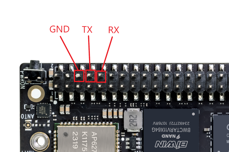
We don’t have a 3-pin debugging interface on BPI-M7, so if you want to use ttl line debugging, you can only connect to 40pin.
Connect pins 6, 8, and 10 on the 40pin.
The serial port baud rate is 1500000. Don’t make the wrong choice.
¶ Flash image
| Choosing the Burning Method : Rockchip chip Flash System Image |
¶ Interface Settings
If you are using Banana Pi BPI-M5 Pro for the first time, please familiarize yourself with the Peripheral Interfaces for better understanding of the following content.
¶ Debug Serial Port
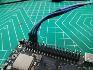
Connect the USB to TTL serial cable as follows, and BAUD=1500000:
| BPI-M5 Pro | Connect | Serial Module |
|---|---|---|
GND (pin 6) |
←-→ |
GND |
TX (pin 8) |
←-→ |
RX |
RX (pin 10) |
←-→ |
TX |
¶ Ethernet Port
-
1.First, plug one end of the network cable into the Ethernet port of the ArmSoM-SigeX, and connect the other end to a router. Ensure that the network is functional.
-
2.After the system boots, it will automatically assign an IP address to the Ethernet port via DHCP without any additional configuration.
-
3.To check the IP address in the ArmSoM-SigeX Linux system, use the following command:
armsom@armsom-sige7:~$ ip a
1: lo: <LOOPBACK,UP,LOWER_UP> mtu 65536 qdisc noqueue state UNKNOWN group default qlen 1000
    link/loopback 00:00:00:00:00:00 brd 00:00:00:00:00:00
    inet 127.0.0.1/8 scope host lo
       valid_lft forever preferred_lft forever
    inet6 ::1/128 scope host
       valid_lft forever preferred_lft forever
2: enP4p65s0: <BROADCAST,MULTICAST,UP,LOWER_UP> mtu 1500 qdisc mq state UP group default qlen 1000
    link/ether c6:9c:b0:7e:2b:1f brd ff:ff:ff:ff:ff:ff permaddr aa:a6:84:1b:0d:21
    inet 192.168.10.54/24 brd 192.168.10.255 scope global dynamic noprefixroute enP4p65s0
       valid_lft 86221sec preferred_lft 86221sec
    inet6 fe80::5bb0:d96f:926d:b334/64 scope link noprefixroute
       valid_lft forever preferred_lft forever
3: enP2p33s0: <NO-CARRIER,BROADCAST,MULTICAST,UP> mtu 1500 qdisc mq state DOWN group default qlen 1000
    link/ether be:ed:22:01:47:d9 brd ff:ff:ff:ff:ff:ff permaddr a2:fb:fa:79:de:fb
4: wlan0: <NO-CARRIER,BROADCAST,MULTICAST,UP,LOWER_UP> mtu 1500 qdisc pfifo_fast state DORMANT group default qlen 1000
link/ether b8:2d:28:5a:52:6a brd ff:ff:ff:ff:ff:ffThere are three ways to check the IP address of Rockchip product after it starts:
-
Connect an HDMI monitor, log into the system, and use the terminal command ip a to view the IP address.
-
Use the debug serial port terminal and enter the ip a command to check the IP address.
-
If neither the debug serial port nor HDMI monitor is available, you can check the IP address of the ArmSoM-SigeX Ethernet port through the router’s management interface. However, this method may sometimes fail to display the ArmSoM-SigeX IP address. If you cannot see it, try the following troubleshooting steps:
-
Check if the Linux system has started properly. If the green light on the ArmSoM-SigeX is steady, it generally means the system has booted correctly; if only the red light is on, the system has not booted properly.
-
Ensure the network cable is securely connected, or try a different cable. Try using a different router. Common issues with routers include inability to assign IP addresses or assigning them correctly but not showing them in the router’s interface.
-
If no alternative router is available, use an HDMI monitor or the debug serial port to check the IP address.
-
| Note that DHCP automatically assigning an IP address to the Rockchip product requires no additional configuration. |
-
4.Use the ping tool to check network connectivity.
-
The command to test network connectivity is shown below. You can stop the ping command with the Ctrl+C shortcut.
-
armsom@armsom-sige7:~$ ping www.baidu.com
PING www.a.shifen.com (183.2.172.185): 56 data bytes
64 bytes from 183.2.172.185: icmp_seq=0 ttl=53 time=8.370 ms
64 bytes from 183.2.172.185: icmp_seq=1 ttl=53 time=8.917 ms
64 bytes from 183.2.172.185: icmp_seq=2 ttl=53 time=8.511 ms
64 bytes from 183.2.172.185: icmp_seq=3 ttl=53 time=8.673 ms
^C
--- www.a.shifen.com ping statistics ---
4 packets transmitted, 4 packets received, 0% packet loss
round-trip min/avg/max/stddev = 8.370/8.618/8.917/0.203 ms¶ WIFI
The Banana Pi design with Rockchip series products come with an onboard WIFI module, so there’s no need for external network devices. They use a standard 4th-generation antenna.
¶ Connecting to WIFI via Command Line on Server Image
1.First, log in to the Linux system using one of the following methods:
-
If the board is connected to a network cable, you can log in remotely via SSH.
-
If the board is connected via a debug serial port, use a serial terminal to log in to the Linux system.
-
If the board is connected to an HDMI monitor, you can log in to the Linux system via the HDMI display.
2.Use the nmcli dev wifi command to scan for available WIFI hotspots:
# 1. Enable WIFI
armsom@armsom-sige:/# nmcli r wifi on
# 2. Scan for WIFI
armsom@armsom-sige:/# nmcli dev wifi
# 3. Connect to a WIFI network
armsom@armsom-sige:/# nmcli dev wifi connect "wifi_name" password "wifi_password"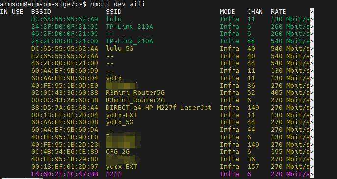
3.Use the nmcli command to connect to the scanned WIFI:
-
Replace wifi_name with the name of the WIFI hotspot you want to connect to.
-
Replace wifi_password with the password for the WIFI hotspot.
armsom@armsom-sige7:~$ nmcli dev wifi connect "ydtx_5G" password "ydtx123456"
Device 'wlan0' successfully activated with "wlan0b6d10bba-e1d5-4b6d-a17f-7d5ab44bbb6f".4.Use the ip addr show wlan0 command to view the WIFI IP address:
armsom@armsom-sige7:~$ ip addr show wlan0
4: wlan0: <BROADCAST,MULTICAST,UP,LOWER_UP> mtu 1500 qdisc pfifo_fast state UP group default qlen 1000
    link/ether b8:2d:28:5a:52:6a brd ff:ff:ff:ff:ff:ff
    inet 192.168.10.9/24 brd 192.168.10.255 scope global dynamic noprefixroute wlan0
       valid_lft 86321sec preferred_lft 86321sec
    inet6 fe80::850d:3119:e0:afa3/64 scope link noprefixroute
valid_lft forever preferred_lft forever5.Use the ping command to test the WIFI network connectivity. You can interrupt the ping command with the Ctrl+C shortcut:
armsom@armsom-sige7:~$ ping www.baidu.com
PING www.a.shifen.com (183.2.172.185): 56 data bytes
64 bytes from 183.2.172.185: icmp_seq=0 ttl=53 time=8.370 ms
64 bytes from 183.2.172.185: icmp_seq=1 ttl=53 time=8.917 ms
64 bytes from 183.2.172.185: icmp_seq=2 ttl=53 time=8.511 ms
64 bytes from 183.2.172.185: icmp_seq=3 ttl=53 time=8.673 ms
^C
--- www.a.shifen.com ping statistics ---
4 packets transmitted, 4 packets received, 0% packet loss
round-trip min/avg/max/stddev = 8.370/8.618/8.917/0.203 ms¶ Connecting to WIFI via GUI on Server Image
1.Log in to the Linux system using one of the following methods:
-
If the development board is connected to a network cable, you can log in remotely via SSH.
-
If the development board is connected via a debug serial port, use a serial terminal to log in to the Linux system (use MobaXterm for serial software, as minicom cannot display the graphical interface).
-
If the development board is connected to an HDMI monitor, log in to the Linux system via the HDMI display.
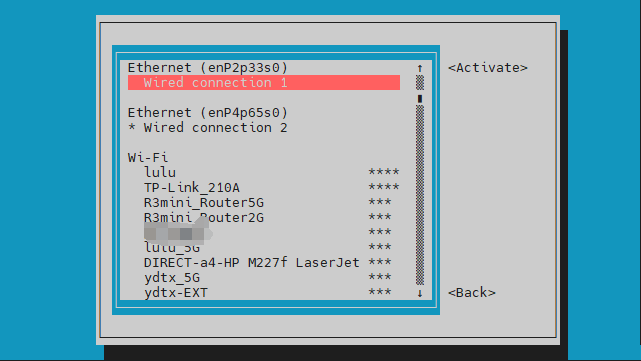
2.Enter the nmtui command in the terminal to open the WIFI connection interface:
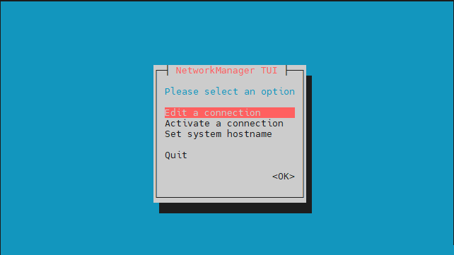
armsom@armsom-sige7:~$ nmtui3.Select "Activate a connection" and press Enter:
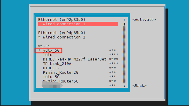
4.Choose the WIFI hotspot you want to connect to and enter the password. After a successful connection, an asterisk “*” will appear next to the connected WIFI name:
5.Use the ip addr show wlan0 command to view the WIFI IP address:
armsom@armsom-sige7:~$ ip addr show wlan0
4: wlan0: <BROADCAST,MULTICAST,UP,LOWER_UP> mtu 1500 qdisc pfifo_fast state UP group default qlen 1000
    link/ether b8:2d:28:5a:52:6a brd ff:ff:ff:ff:ff:ff
    inet 192.168.10.9/24 brd 192.168.10.255 scope global dynamic noprefixroute wlan0
       valid_lft 86316sec preferred_lft 86316sec
    inet6 fe80::a422:3494:3147:92d/64 scope link noprefixroute
valid_lft forever preferred_lft forever6.Use the ping command to test the WIFI network connectivity. You can interrupt the ping command with the Ctrl+C shortcut:
armsom@armsom-sige7:~$ ping www.baidu.com
PING www.a.shifen.com (183.2.172.185): 56 data bytes
64 bytes from 183.2.172.185: icmp_seq=0 ttl=53 time=8.370 ms
64 bytes from 183.2.172.185: icmp_seq=1 ttl=53 time=8.917 ms
64 bytes from 183.2.172.185: icmp_seq=2 ttl=53 time=8.511 ms
64 bytes from 183.2.172.185: icmp_seq=3 ttl=53 time=8.673 ms
^C
--- www.a.shifen.com ping statistics ---
4 packets transmitted, 4 packets received, 0% packet loss
round-trip min/avg/max/stddev = 8.370/8.618/8.917/0.203 ms¶ Testing Method for Desktop Image
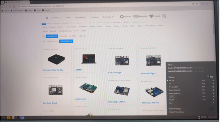
1.Click the network configuration icon on the desktop (ensure not to connect a network cable while testing WIFI).
2.After connecting to WIFI, open a browser to check if you can access the internet:
¶ BT
# 1. Activate Bluetooth
armsom@armsom-sige5:/# service bluetooth start
# 2. Enter bluetoothctl
armsom@armsom-sige5:/# bluetoothctl
# 3. Enter the following command to connect
armsom@armsom-sige5:/# power on
armsom@armsom-sige5:/# agent on
armsom@armsom-sige5:/# default-agent
armsom@armsom-sige5:/# scan on
armsom@armsom-sige5:/# pair yourDeviceMAC¶ HDMI
The BPI-M5 Pro has an HDMI output port which supports CEC and HDMI 2.1, maximum resolution up to 4Kp120.
| Model | BPI-M7 | BPI-M5 Pro | BPI-M1 Pro |
|---|---|---|---|
Resolution |
8Kp60 |
4Kp120 |
4Kp60 |
Connect the board to an HDMI display using an HDMI cable.
After booting the Linux system, if the HDMI display shows an image, the HDMI interface is functioning correctly.
| that many laptops, while having HDMI ports, typically have HDMI output only and do not support HDMI in. This means you cannot display the HDMI output from another device on the laptop’s screen. Before connecting the development board’s HDMI to a laptop’s HDMI port, ensure your laptop supports HDMI in functionality. If there is no display, first check if your system is a desktop version; server versions might only show a terminal. |
-
1.HDMI to VGA Display Test
-
Required accessories:
-
HDMI to VGA converter
-
-
2.A VGA cable and a display with a VGA port
The HDMI to VGA display test is shown below:
| When using HDMI to VGA conversion, no additional configuration is needed for the ArmSoM-Sige products or the Linux system. If you encounter issues, check the HDMI to VGA converter, VGA cable, and display for problems. |
¶ USB
The BPI-M5 Pro provides one USB 2.0 and one USB 3.0 port.
| Model | BPI-M7 | BPI-M5 Pro | BPI-M1 Super |
|---|---|---|---|
USB |
1x Type-C 3.0, 1x USB3.0, 1x USB2.0 |
1x Type-C 3.0, 1x USB3.0, 1x USB2.0 |
2x USB2.0 |
| USB interfaces can be expanded by using a USB hub. |
¶ Testing USB Mouse or Keyboard
-
1.Insert a USB keyboard into the board’s USB port.
-
2.Connect the board to an HDMI display.
-
3.If the mouse or keyboard operates the system normally, the USB interface is working correctly (the mouse will only work in desktop versions of the system).
¶ Testing USB Storage Device
-
1.Insert a USB flash drive or USB external hard drive into the ArmSoM-Sige product’s USB port.
-
2.Run the following command; if you see sdX output, the USB drive is recognized successfully:
armsom@armsom-sige7:/# cat /proc/partitions | grep "sd*"
major minor  #blocks  name
8 0 122880000 sda-
3.Use the mount command to mount the USB drive to /mnt and view the files on the USB drive:
armsom@armsom-sige7:/# sudo mount /dev/sda1 /test/-
4.After mounting, use the df -h command to check the USB drive’s capacity usage and mount point:
armsom@armsom-sige7:/test# df -h | grep "sd"
/dev/sda 4.7G 4.7G 0 100% /test¶ USB Camera
-
1.Prepare a USB camera that supports the UVC protocol and connect it to the board’s USB port.
-
2.Use the v4l2-ctl command to view the USB camera’s device node information, which should be /dev/video0:
armsom@armsom-sige7:/# v4l2-ctl --list-devices
Logitech HD Webcam C93 (usb-xhci-hcd.5.auto-1):
        /dev/video40
        /dev/video41
/dev/media4-
3.On a desktop system, you can use Cheese/V4L2 test bench to open the USB camera directly.
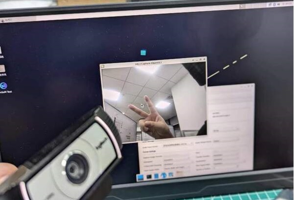
You can also use terminal commands to preview the camera:
armsom@armsom-sige7:/# gst-launch-1.0 v4l2src device=/dev/video0 io-mode=4 ! videoconvert ! video/x-raw,format=NV12,width=1920,height=1080 ! xvimagesink;To capture a photo:
armsom@armsom-sige7:/# gst-launch-1.0 v4l2src device=/dev/video0 io-mode=4 ! videoconvert ! video/x-raw,format=NV12,width=1920,height=1080 ! jpegenc ! multifilesink location=/home/armsom/test.jpg;To record a video:
gst-launch-1.0 v4l2src num-buffers=512 device=/dev/video0 io-mode=4 ! videoconvert ! video/x-raw, format=NV12, width=1920, height=1080, framerate=30/1 ! tee name=t ! queue ! mpph264enc ! queue ! h264parse ! mpegtsmux ! filesink location=/home/armsom/test.mp4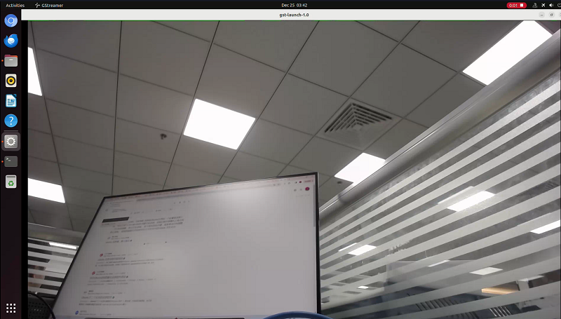
¶ Audio
View sound cards in the system:
armsom@armsom-sige5:/# aplay -l
**** List of PLAYBACK Hardware Devices ****
card 0: rockchipdp0 [rockchip,dp0], device 0: rockchip,dp0 spdif-hifi-0 [rockchip,dp0 spdif-hifi-0]
 Subdevices: 1/1
 Subdevice #0: subdevice #0
card 1: rockchipes8316 [rockchip-es8316], device 0: fe470000.i2s-ES8316 HiFi es8316.7-0011-0 [fe470000.i2s-ES8316 HiFi es8316.7-0011-0]
  Subdevices: 1/1
  Subdevice #0: subdevice #0
card 2: rockchiphdmi0 [rockchip-hdmi0], device 0: rockchip-hdmi0 i2s-hifi-0 [rockchip-hdmi0 i2s-hifi-0]
  Subdevices: 1/1
Subdevice #0: subdevice #0¶ Fan
BPI-M5 Pro products are equipped with a 5V fan using a 0.8mm connector.
The fan currently operates in five default states:
| Temperature Range | State | PWM Speed |
|---|---|---|
Less than 50°C |
0 |
0 |
50°C - 55°C |
1 |
50 |
55°C - 60°C |
2 |
100 |
60°C - 65°C |
3 |
150 |
65°C - 70°C |
4 |
200 |
Above 70°C |
5 |
250 |
armsom@armsom-sige5:/# echo 100 > /sys/devices/platform/pwm-fan/hwmon/hwmon6/pwm1¶ Type-C
The BPI-M5 Pro features a full-featured USB Type‐C 3.0 port which supports up to 8K@30fps DP display.
¶ 40Pin
The BPI-M5 Pro/BPI-M7 provides a 40-pin GPIO header, compatible with most sensors on the market.
¶ Wiring-armbian Instructions
Download the wiringOP code from wiring-armbian: https://github.com/ArmSoM/wiring-armbian
-
Test the output of the gpio readall command as shown below:
+------+-----+----------+--------+---+  ArmSoM-Sige7(BPI-M7) +---+--------+----------+-----+------+
| GPIO | wPi |   Name   |  Mode  | V | Physical | V |  Mode  | Name     | wPi | GPIO |
+------+-----+----------+--------+---+----++----+---+--------+----------+-----+------+
|      |     |     3.3V |        |   |  1 || 2  |   |        | 5V       |     |      |
|  139 |   0 |    SDA.7 |     IN | 1 |  3 || 4  |   |        | 5V       |     |      |
|  138 |   1 |    SCL.7 |     IN | 1 |  5 || 6  |   |        | GND      |     |      |
|  115 |   2 |    PWM15 |    OUT | 0 |  7 || 8  | 1 | ALT10  | GPIO0_B5 | 3   | 13   |
|      |     |      GND |        |   |  9 || 10 | 1 | ALT10  | GPIO0_B6 | 4   | 14   |
|  113 |   5 | GPIO3_C1 |     IN | 0 | 11 || 12 | 1 | IN     | GPIO3_B5 | 6   | 109  |
|  111 |   7 | GPIO3_B7 |     IN | 0 | 13 || 14 |   |        | GND      |     |      |
|  112 |   8 | GPIO3_C0 |     IN | 0 | 15 || 16 | 0 | IN     | GPIO3_A4 | 9   | 100  |
|      |     |     3.3V |        |   | 17 || 18 | 1 | IN     | GPIO4_C4 | 10  | 148  |
|   42 |  11 | SPI0_TXD |     IN | 1 | 19 || 20 |   |        | GND      |     |      |
|   41 |  12 | SPI0_RXD |     IN | 1 | 21 || 22 |   |        | SARADC_IN4 |     |      |
|   43 |  14 | SPI0_CLK |     IN | 1 | 23 || 24 | 1 | IN     | SPI0_CS0 | 15  | 44   |
|      |     |      GND |        |   | 25 || 26 | 1 | IN     | SPI0_CS1 | 16  | 45   |
|  150 |  17 | GPIO4_C6 |     IN | 1 | 27 || 28 | 0 | OUT    | GPIO4_C5 | 18  | 149  |
|   63 |  19 | GPIO1_D7 |     IN | 1 | 29 || 30 |   |        | GND      |     |      |
|   47 |  20 | GPIO1_B7 |     IN | 1 | 31 || 32 | 0 | IN     | GPIO3_C2 | 21  | 114  |
|  103 |  22 | GPIO3_A7 |     IN | 1 | 33 || 34 |   |        | GND      |     |      |
|  110 |  23 | GPIO3_B6 |     IN | 0 | 35 || 36 | 0 | IN     | GPIO3_B1 | 24  | 105  |
|    0 |  25 | GPIO0_A0 |     IN | 1 | 37 || 38 | 0 | IN     | GPIO3_B2 | 26  | 106  |
|      |     |      GND |        |   | 39 || 40 | 1 | IN     | GPIO3_B3 | 27  | 107  |
+------+-----+----------+--------+---+----++----+---+--------+----------+-----+------+
| GPIO | wPi |   Name   |  Mode  | V | Physical | V |  Mode  | Name     | wPi | GPIO |
+------+-----+----------+--------+---+  ArmSoM-Sige7(BPI-M7) +---+--------+----------+-----+------+
-
Set the GPIO pin to output mode. The third parameter requires the wPi number corresponding to the pin.
root@armsom-sige7:~/wiring-armbian# gpio mode 2 out-
Set the GPIO pin to output a low level. After setting, you can measure the voltage on the pin with a multimeter; if it reads 0V, the low level is set successfully.
root@armsom-sige7:~/wiring-armbian# gpio write 2 0-
Set the GPIO pin to output a high level. After setting, you can measure the voltage on the pin with a multimeter; if it reads 3.3V, the high level is set successfully.
root@armsom-sige7:~/wiring-armbian# gpio write 2 1-
The setup method for other pins is similar; just change the wPi number to the corresponding pin’s number.
¶ RGB LED
The BPI-M5 Pro has two user LEDs - green and red.
-
User Green LED Constantly indicates running kernel by default.
-
User Red LED Off by default, can be controlled by user.
Users can control with commands:
armsom@armsom-sige5:/# sudo su
armsom@armsom-sige5:/# echo timer > /sys/class/leds/red/trigger
armsom@armsom-sige5:/# echo activity > /sys/class/leds/red/trigger¶ RTC
-
The BPI-M5 Pro features an LK8563S RTC chip.
-
First, insert the RTC battery using the 2-pin 0.8mm header to supply power to the RTC IC.
| that we should keep the RTC battery in the RTC connector and confirm the rtc LK8563S device which has been created. |
armsom@armsom-sige5:/# dmesg | grep rtc
[ 6.407133] rtc-hym8563 6-0051: rtc information is valid
[ 6.412731] rtc-hym8563 6-0051: registered as rtc0
[ 6.413779] rtc-hym8563 6-0051: setting system clock to 2022-06-22T01:22:26 UTC (1655860946)-
Find rtc0, then use the following commands to set system time and sync to rtc0:
armsom@armsom-sige5:/# hwclock -r
2023-11-03 10:32:40.461910+00:00
armsom@armsom-sige5:/# date
Fri 3rd Nov 10:33:12 UTC 2023
armsom@armsom-sige5:/# hwclock -w
armsom@armsom-sige5:/# hwclock -r
armsom@armsom-sige5:/# poweroff-
Turn off the RTC battery for 10+ minutes, insert the battery again and boot Sige5, and check if RTC synced with system clock:
armsom@armsom-sige5:/# hwclock -r
2023-11-03 10:35:40.461910+00:00
armsom@armsom-sige5:/# date
Fri 3rd Nov 10:36:01 UTC 2023¶ M.2 interface
BPI-M5 Pro provides an M.2 connector:
The back of the product features an M.2 M Key connector with a PCIe 2.0 interface supporting 1 channel. The board includes a standard M.2 2280 mounting hole, allowing for the deployment of an M.2 2280 NVMe SSD.
| This M.2 interface does not support M.2 SATA SSDs. |
armsom@armsom-sige5:/# mkdir temp
armsom@armsom-sige5:/# mount /dev/nvme0n1 temp¶ MIPI-CSI
¶ IMX415
Use the IMX415 module for the camera. After connecting and powering on the camera module you can view the boot log:
armsom@armsom-sige5:/# dmesg | grep imx415
[    2.547754] imx415 3-001a: driver version: 00.01.08
[    2.547767] imx415 3-001a:  Get hdr mode failed! no hdr default
[    2.547819] imx415 3-001a: Failed to get power-gpios
[    2.547826] imx415 3-001a: could not get default pinstate
[    2.547831] imx415 3-001a: could not get sleep pinstate
[    2.547850] imx415 3-001a: supply dvdd not found, using dummy regulator
[    2.547918] imx415 3-001a: supply dovdd not found, using dummy regulator
[    2.547945] imx415 3-001a: supply avdd not found, using dummy regulator
[    2.613843] imx415 3-001a: Detected imx415 id 0000e0
[    2.613890] rockchip-csi2-dphy csi2-dphy0: dphy0 matches m00_b_imx415 3-001a:bus type 5
[   18.386174] imx415 3-001a: set fmt: cur_mode: 3864x2192, hdr: 0
[ 18.389067] imx415 3-001a: set exposure(shr0) 2047 = cur_vts(2250) - val(203)Use v4l2-ctl for image capture:
/ MIPI-CSI1
armsom@armsom-sige5:/# v4l2-ctl -d /dev/video31 --set-fmt-video=width=3840,height=2160,pixelformat=NV12 --stream-mmap=3 --stream-skip=60 --stream-to=/tmp/cif73.out --stream-count=3 --stream-poll

// MIPI-CSI2
armsom@armsom-sige5:/# v4l2-ctl -d /dev/video22 --set-fmt-video=width=3840,height=2160,pixelformat=NV12 --stream-mmap=3 --stream-skip=60 --stream-to=/tmp/cif73.out --stream-count=3 --stream-pollRecord video directly with gst-launch-1.0:
// MIPI-CSI1
armsom@armsom-sige5:/# gst-launch-1.0 v4l2src device=/dev/video31 ! video/x-raw,format=NV12,width=3840,height=2160, framerate=30/1 ! xvimagesink

// MIPI-CSI2
armsom@armsom-sige5:/# gst-launch-1.0 v4l2src device=/dev/video22 ! video/x-raw,format=NV12,width=3840,height=2160, framerate=30/1 ! xvimagesink¶ ov13850
This module is similar to IMX415 and is as follows:
The camera uses the ov13850. After connecting and powering on the camera module, you can view the boot log.
root@armsom-sige7:/# dmesg | grep ov13850
[    2.302905] ov13850 5-0010: driver version: 00.01.05
[    2.302944] ov13850 5-0010: Failed to get power-gpios, maybe no use
[    2.303067] ov13850 5-0010: supply avdd not found, using dummy regulator
[    2.303153] ov13850 5-0010: supply dovdd not found, using dummy regulator
[    2.303186] ov13850 5-0010: supply dvdd not found, using dummy regulator
[    2.303213] ov13850 5-0010: could not get default pinstate
[    2.303220] ov13850 5-0010: could not get sleep pinstate
[    2.308532] ov13850 5-0010: Detected OV00d850 sensor, REVISION 0xb2
[    2.332058] ov13850 5-0010: Consider updating driver ov13850 to match on endpoints
[ 2.332084] rockchip-csi2-dphy csi2-dphy0: dphy0 matches m00_b_ov13850 5-0010:bus type 5Use v4l2-ctl for image capture:
// MIPI-CSI1
root@armsom-sige7:/# v4l2-ctl -d /dev/video31 --set-selection=target=crop,top=0,left=0,width=2112,height=1568 --set-fmt-video=width=2112,height=1568,pixelformat=NV12 --stream-mmap=3 --stream-to=/nv12.bin --stream-count=1 --stream-poll

// MIPI-CSI2
root@armsom-sige7:/# v4l2-ctl -d /dev/video22 --set-selection=target=crop,top=0,left=0,width=2112,height=1568 --set-fmt-video=width=2112,height=1568,pixelformat=NV12 --stream-mmap=3 --stream-to=/nv12.bin --stream-count=1 --stream-pollRecord video using gst-launch-1.0
// MIPI-CSI1
root@armsom-sige7:/# gst-launch-1.0 v4l2src device=/dev/video31 ! video/x-raw,format=NV12,width=2112,height=1568, framerate=30/1 ! xvimagesink

// MIPI-CSI2
root@armsom-sige7:/# gst-launch-1.0 v4l2src device=/dev/video22 ! video/x-raw,format=NV12,width=2112,height=1568, framerate=30/1 ! xvimagesink
root@armsom-sige7:/# gst-launch-1.0 v4l2src device=/dev/video0 ! video/x-raw,format=NV12,width=2112,height=1568, framerate=30/1 ! xvimagesink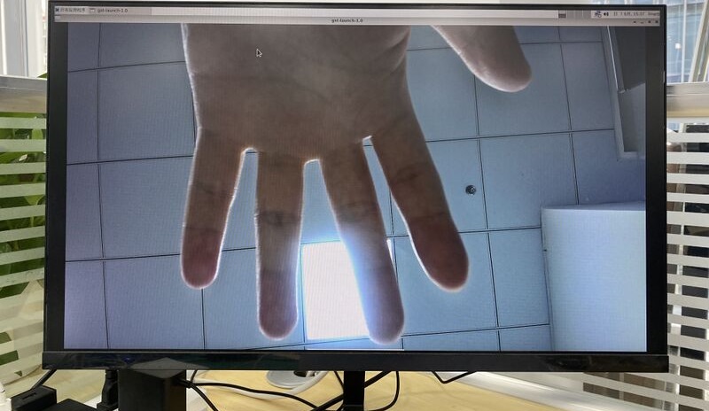
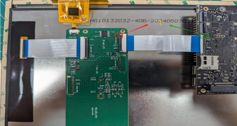
¶ MIPI DSI
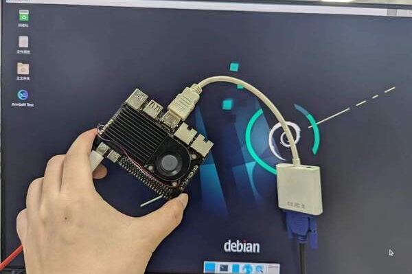
BPI-M7 supports a maximum resolution of 4K@120Hz.
-
1.Connect the cables as shown in the image below.
-
2.Configuring the 10.1-inch MIPI LCD screen
-
By default, the Linux image does not have the MIPI LCD screen configuration enabled. To use the MIPI LCD screen, you need to enable it manually.
-
Use nano to open the /boot/armbianEnv.txt file:
-
sudo nano /boot/armbianEnv.txt-
In this file, find or add the keyword "overlays=".
// Choose according to your product
overlays=armsom-sige7-display-10hd // Sige7
overlays=armsom-sige5-display-10hd // Sige5
overlays=armsom-sige3-display-10hd // Sige3Shortcut keys: Ctrl + S to save Ctrl + X to exit
After editing, restart the device to apply the Overlays settings and support Display 10 HD.
¶ CPU/GPU/NPU/DDR
The following example uses BPI-M7 to illustrate how to set the fixed frequency and performance modes for CPU, GPU, NPU, and DDR.
¶ Fixed Frequency Settings
¶ CPU Fixed Frequency
The BPI-M7 CPU consists of 4 A55 cores and 4 A76 cores, managed in three separate groups. The nodes are as follows:
/sys/devices/system/cpu/cpufreq/policy0: (corresponding to 4 A55: CPU0-3)
affected_cpus     cpuinfo_max_freq  cpuinfo_transition_latency  scaling_available_frequencies  scaling_cur_freq  scaling_governor  scaling_min_freq  stats
cpuinfo_cur_freq  cpuinfo_min_freq  related_cpus                scaling_available_governors    scaling_driver    scaling_max_freq  scaling_setspeed

/sys/devices/system/cpu/cpufreq/policy4: (corresponding to 2 A76: CPU4-5)
affected_cpus     cpuinfo_max_freq  cpuinfo_transition_latency  scaling_available_frequencies  scaling_cur_freq  scaling_governor  scaling_min_freq  stats
cpuinfo_cur_freq  cpuinfo_min_freq  related_cpus                scaling_available_governors    scaling_driver    scaling_max_freq  scaling_setspeed

/sys/devices/system/cpu/cpufreq/policy6: (corresponding to 2 A76: CPU6-7)
affected_cpus     cpuinfo_max_freq  cpuinfo_transition_latency  scaling_available_frequencies  scaling_cur_freq  scaling_governor  scaling_min_freq  stats
cpuinfo_cur_freq  cpuinfo_min_freq  related_cpus                scaling_available_governors    scaling_driver    scaling_max_freq  scaling_setspeed

root@armsom-sige7:/ # cat /sys/devices/system/cpu/cpufreq/policy6/scaling_available_frequencies // Get current supported CPU frequencies
408000 600000 816000 1008000 1200000 1416000 1608000 1800000 2016000 2208000 2400000
root@armsom-sige7:/ # cat /sys/devices/system/cpu/cpufreq/policy6/scaling_available_governors // Get CPU operating modes
conservative ondemand userspace powersave performance schedutilThe default is the automatic frequency scaling mode: schedutil (to restore, set to this mode).
Manual Fixed Frequency Settings
root@armsom-sige7:/ $ su
root@armsom-sige7:/ # echo userspace > /sys/devices/system/cpu/cpufreq/policy6/scaling_governor // Manual fixed frequency mode: userspace
root@armsom-sige7:/ # echo 2016000 > /sys/devices/system/cpu/cpufreq/policy6/scaling_setspeed // Set frequency to 2016000
root@armsom-sige7:/ # cat /sys/devices/system/cpu/cpufreq/policy6/cpuinfo_cur_freq // Verify if set successfully
2016000The other two CPU groups can be set similarly by operating the corresponding nodes.
¶ GPU Fixed Frequency
GPU Node Path
root@armsom-sige7:/ # ls /sys/class/devfreq/fb000000.gpu/
available_frequencies  cur_freq  governor  max_freq  name              power      target_freq  trans_stat
available_governors    device    load      min_freq  polling_interval  subsystem  timer        uevent
root@armsom-sige7:/ # cat /sys/class/devfreq/fb000000.gpu/available_frequencies  // Get supported GPU frequencies
1000000000 900000000 800000000 700000000 600000000 500000000 400000000 300000000 200000000
root@armsom-sige7:/ # cat /sys/class/devfreq/fb000000.gpu/available_governors // Get GPU operating modes
dmc_ondemand userspace powersave performance simple_ondemandThe default is the automatic frequency scaling mode: simple_ondemand (to restore, set to this mode).
Manual Fixed Frequency Settings
root@armsom-sige7:/ $ su
root@armsom-sige7:/ # echo userspace > /sys/class/devfreq/fb000000.gpu/governor // Manual fixed frequency mode: userspace
root@armsom-sige7:/ # echo 1000000000 > /sys/class/devfreq/fb000000.gpu/userspace/set_freq // Set frequency to 1000000000
root@armsom-sige7:/ # cat /sys/class/devfreq/fb000000.gpu/cur_freq  // Verify if set successfully
1000000000
root@armsom-sige7:/ # cat /sys/class/devfreq/fb000000.gpu/load   // Check GPU load
28@300000000Hz¶ DDR Fixed Frequency
DDR Node Path
root@armsom-sige7:/ # ls /sys/class/devfreq/dmc/
available_frequencies  cur_freq  downdifferential  load      min_freq  polling_interval  subsystem      target_freq  trans_stat  upthreshold
available_governors    device    governor          max_freq  name      power             system_status  timer        uevent
root@armsom-sige7:/ # cat /sys/class/devfreq/dmc/available_frequencies // Get supported DDR frequencies
528000000 1068000000 1560000000 2112000000
root@armsom-sige7:/ # cat /sys/class/devfreq/dmc/available_governors // Get DDR operating modes
dmc_ondemand userspace powersave performance simple_ondemandThe default is the automatic frequency scaling mode: dmc_ondemand (to restore, set to this mode).
Manual Fixed Frequency Settings
root@armsom-sige7:/ $ su
root@armsom-sige7:/ # echo userspace > /sys/class/devfreq/dmc/governor // Manual fixed frequency mode: userspace
root@armsom-sige7:/ # echo 2112000000 > /sys/class/devfreq/dmc/userspace/set_freq  // Set frequency to 2112000000
root@armsom-sige7:/ # cat /sys/class/devfreq/dmc/cur_freq   // Verify if set successfully
2112000000
root@armsom-sige7:/ # cat /sys/class/devfreq/dmc/load  // Check DDR load
7@528000000Hz¶ NPU Fixed Frequency
NPU Node Path
root@armsom-sige7:/ # ls /sys/class/devfreq/fdab0000.npu/
available_frequencies  cur_freq  governor  max_freq  name              power      target_freq  trans_stat  userspace
available_governors    device    load      min_freq  polling_interval  subsystem  timer        uevent
root@armsom-sige7:/ # cat /sys/class/devfreq/fdab0000.npu/available_frequencies     // Get supported NPU frequencies
200000000 300000000 400000000 500000000 600000000 700000000 800000000 900000000 1000000000
root@armsom-sige7:/ # cat /sys/class/devfreq/fdab0000.npu/available_governors // Get NPU operating modes
dmc_ondemand userspace powersave performance simple_ondemandThe default is the automatic frequency scaling mode: simple_ondemand (to restore, set to this mode).
Manual Fixed Frequency Settings
root@armsom-sige7:/ $ su
root@armsom-sige7:/ # echo userspace > /sys/class/devfreq/fdab0000.npu/governor // Manual fixed frequency mode: userspace
root@armsom-sige7:/ # echo 1000000000 > /sys/class/devfreq/fdab0000.npu/userspace/set_freq // Set frequency to 1000000000
root@armsom-sige7:/ # cat /sys/class/devfreq/fdab0000.npu/cur_freq  // Verify if set successfully
1000000000
root@armsom-sige7:/ # cat /sys/kernel/debug/rknpu/load // Check NPU load
NPU load: Core0: 0%, Core1: 0%, Core2: 0%,¶ Performance Modes
root@armsom-sige7:/ $ su
root@armsom-sige7:/ # echo performance > /sys/devices/system/cpu/cpufreq/policy6/scaling_governor
root@armsom-sige7:/ # echo performance > /sys/class/devfreq/fb000000.gpu/governor
root@armsom-sige7:/ # echo performance > /sys/class/devfreq/dmc/governor
root@armsom-sige7:/ # echo performance > /sys/class/devfreq/fdab0000.npu/governor¶ AI development
¶ RKLLM
| How to use RKLLM : Banana Pi BPI-M7 RKLLM Development |
¶ Notes
| ELECTROSTATIC PROTECTION |
-
Before handling the device, please ensure you wear an anti-static wrist strap or take electrostatic discharge measures to prevent damage to the development board.
-
Assembly should be performed in an electrostatic-safe environment, avoiding operations in dry and low-humidity conditions.
-
When not in use, store the device in an anti-static bag and keep it in a suitably temperature-controlled, low-humidity environment to prevent static electricity buildup.
-
When handling the device, avoid friction or collisions to prevent the generation of static electricity that could cause damage.
-
When holding the device, try to avoid direct contact with the chips on the mainboard to prevent static damage.
-
Do not plug or unplug wires or other devices while the device is operating to avoid damage from electrical surges.
-
When connecting or disconnecting the GPIO/MIPI expansion interfaces, make sure to turn off the power and disconnect the power cable to prevent damage from electrical current.
| HEAT MANAGEMENT |
-
Without effective cooling measures, the surface temperature of the main chip may exceed 60 degrees. When handling the device, please avoid direct contact with the SoC and surrounding power inductors to prevent burns. Ensure that the environment is well-ventilated during operation to prevent localized heat buildup, which could lead to overheating. Additionally, do not place the device in direct sunlight. It is recommended to choose between the official cooling fan, heat sink, or third-party cooling kits based on specific usage conditions to ensure optimal cooling performance.