¶ Overview
Banana Pi BPI-R4 Mini Wifi7 smart router board design with MediaTek MT7987A Quad-core Arm Cortex-A53,it support 2GB DDR4 and 8G eMMC Flash on board. 2 x 2.5G RJ45, Wifi7 onboard,Mini Size .
¶ Development
¶ Preparation
-
USB Disk
-
USB TypeC cable
-
CAT6A/Cat5e Ethernet cable
-
12V/5A power adapter(without any peripherals and network cable inset, the power consumption of BPI-R4MINI Main Board is about 10W, so 12V/2A will work. But you need to determine whether you need a higher power power adapter according to your own accessory usage,12V/5A is recommended)
-
Windows/unbuntu system
¶ Bootstrap setting
-
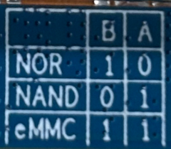
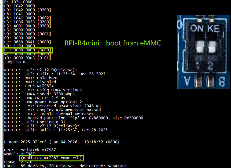
All Jumper is "1", BPI-R4Mini will boot from emmc card
-
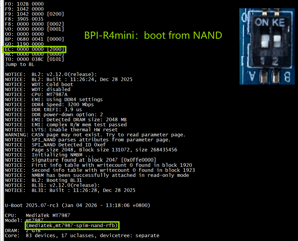
SW3-B is "0" and SW3-A is "1" , BPI-R4Mini will boot from SPI NAND
-
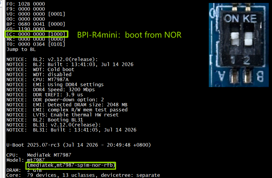
SW3-B is "1" and SW3-A is "0" , BPI-R4Mini will boot from SPI NOR
-
If the console said "system halt!", it means that the bootup storage does not cotain any OS
¶ Flashing image
¶ How to flashing image to NAND Flash
| Factory image information:OpenWrt 24.10-SNAPSHOT Architecture:aarch64_cortex-a53 |
Before flashing image into Nand, please prepare a USB disk. Let’s take OpenWrt image (mtk-bpi-r4mini-NAND-20260721.img) for example, the steps are below:
-
Format the USB disk to FAT32.
-
Copy Nand boot OpenWrt image(mtk-bpi-r4mini-NAND-20260721.img) to USB disk.
-
Change the bootstrap to eMMC boot, then power up the board.
-
Plug in USB disk to the board, and mount the USB to /mnt or other directory as follows: (you can skip mounting if it is mounted automatically)
mount -t vfat /dev/sda1 /mnt cd /mnt -
Execute following command to erase the whole Nand flash and copy image to nand device: Notice:The R4mini’s NAND image is flashed to MTD0
mtdinfo /dev/mtd0 mtd0 Name: spi0.0 Type: nand Eraseblock size: 131072 bytes, 128.0 KiB Amount of eraseblocks: 2048 (268435456 bytes, 256.0 MiB) Minimum input/output unit size: 2048 bytes Sub-page size: 2048 bytes OOB size: 128 bytes Character device major/minor: 90:0 Bad blocks are allowed: true Device is writable: true cat /proc/mtd dev: size erasesize name mtd0: 10000000 00020000 "spi0.0" mtd1: 0f000000 00020000 "nmbm_spim_nand" mtd2: 00480000 00010000 "BL2" mtd3: 00400000 00010000 "Factory" mtd4: 00200000 00010000 "FIP" mtd5: 02000000 00010000 "Kernel" mtd6: 40000000 00010000 "rootfs" mtd7: 3cb90000 00010000 "rootfs_data" mtd8: 80000000 00010000 "usrdata" mtd9: 10f580000 00010000 "bmtpool" flash_erase /dev/mtd0 0 2048 Erasing 128 Kibyte @ ffe0000 -- 100 % complete mtd erase /dev/mtd0 mtd write mtk-bpi-r4mini-NAND-20260721 /dev/mtd0 -
Power off BPI-R4Mini, remove usb disk , change bootstrap to nand boot and power up again.
¶ How to flashing image to eMMC Flash
| It is necessary to switch to NAND startup and then burn the EMMC image into the EMMC. Finally, you will change the bootstrap to boot from EMMC. |
Let’s take OpenWrt image (bl2_emmc-r4mini.img, mtk-bpi-r4mini-EMMC-20260721) for example, the steps are below:
-
Format the USB disk to FAT32.
-
Copy EMMC boot OpenWrt image(bl2_emmc-r4mini.img, mtk-bpi-r4mini-EMMC-20260721) to USB disk, if the image is compressed please uncompress it before copying to USB disk.
-
Change the bootstrap to Nand boot and power up R4Mini.
-
Plug in USB disk to the board, and mount the USB to /mnt or other directory as follows: (you can skip mounting if it is mounted automatically)
mount -t vfat /dev/sda1 /mnt cd /mnt -
Execute command
dmesg | grep mmcblk0 [ 5.778706] mmcblk0: mmc0:0001 8GTF4R 7.28 GiB [ 5.783936] mmcblk0boot0: mmc0:0001 8GTF4R partition 1 4.00 MiB [ 5.790558] mmcblk0boot1: mmc0:0001 8GTF4R partition 2 4.00 MiB [ 5.796568] mmcblk0rpmb: mmc0:0001 8GTF4R partition 3 512 KiB, chardev (245:0) [ 5.831079] mmcblk0: p1 p2 p3 p4 p5 echo 0 > /sys/block/mmcblk0boot0/force_ro dd if=bl2_emmc-r4mini.img of=/dev/mmcblk0boot0 489+1 records in 489+1 records out dd if=mtk-bpi-r4mini-EMMC-20260721.img of=/dev/mm 194335+1 records in 194335+1 records out mmc bootpart enable 1 1 /dev/mmcblk0 sync sync -
Power off BPI-R4Mini, remove u-disk driver, change bootstrap to emmc boot and power up again.
¶ How to recovery system from NOR flash
Method:Recovery emmc system first,then see "How to flashing image to NAND Flash"
-
Make sure that the NOR flash is ready.
-
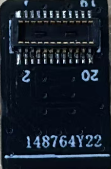
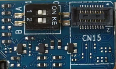
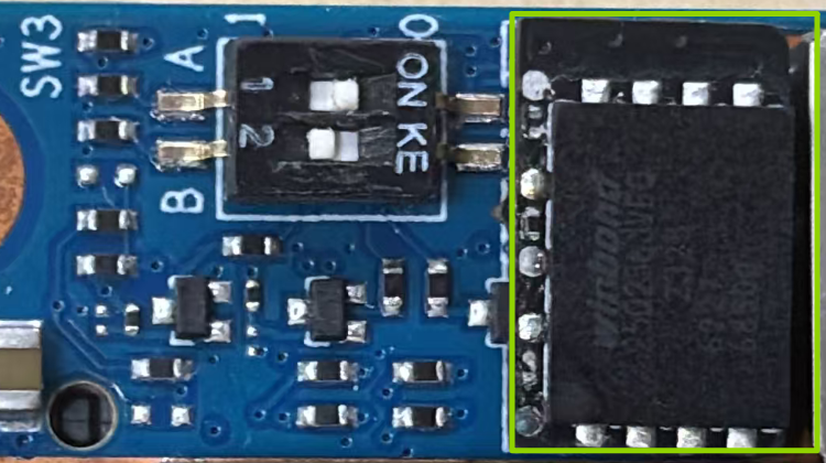
Install the NOR flash to the board(CN15).
NOR Flash:
Before installation:
After installation:
-
Switch the bootstrap to NOR and boot up.
-
Format the USB disk to FAT32.
-
Copy EMMC boot OpenWrt image(bl2_emmc-r4mini.img, mtk-bpi-r4mini-EMMC-20260721) to USB disk,
-
Plug in USB disk to the board, and mount the USB to /mnt or other directory as follows: (you can skip mounting if it is mounted automatically)
mount -t vfat /dev/sda1 /mnt cd /mnt -
Execute command
mtdinfo /dev/mtd0 dmesg | grep mmcblk0 echo 0 > /sys/block/mmcblk0boot0/force_ro dd if=bl2_emmc-r4mini.img of=/dev/mmcblk0boot0 dd if=mtk-bpi-r4mini-EMMC-20260721.img of=/dev/mmcblk0 mmc bootpart enable 1 1 /dev/mmcblk0 sync sync -
Power off BPI-R4Mini, remove u-disk driver, change bootstrap to emmc boot and power up again.
¶ Power ON
-
Using your USB TypeC cable Connect to debug console(CN3) on BPI-R4Mini
-
Install Terminal Emulator or use a serial terminal that you are familiar with,
-
change the setting as follows: Baud=115200,Data bits: 8bit,Parity: none,Stop: 1bit, Flow control: none;
-
Set up the bootstrap before supplying power, (If you are using BPI-R4Mini for the first time, it is recommended to set it to NAND boot)
-
when Connect power adapter to DC-IN connector(CN6),Green LED “PWR” light up,And there will be characters similar to the following on the console. This means you have successfully started BPI-R4Mini.
Details
F0: 102B 0000
F9: 0000 0000
V0: 0000 0000 [0001]
00: 0000 0000
BP: 0680 0041 [0000]
G0: 1190 0000
EC: 0000 0000 [1000]
MK: 0000 0000 [0000]
T0: 0000 0364 [0101]
Jump to BL

NOTICE:  BL2: v2.12.0(release):
NOTICE:  BL2: Built : 13:41:03, Jul 14 2026
NOTICE:  WDT: Cold boot
NOTICE:  WDT: disabled
NOTICE:  CPU: MT7987A
NOTICE:  EMI: Using DDR4 settings
NOTICE:  DDR4 Speed: 3200 Mbps
NOTICE:  DDR tREFI: 3.9 us
NOTICE:  DDR power-down option: 2
NOTICE:  EMI: Detected DRAM size: 2048 MB
NOTICE:  EMI: complex R/W mem test passed
NOTICE:  LVTS: Enable thermal HW reset
NOTICE:  BL2: Booting BL31
NOTICE:  BL31: v2.12.0(release):
NOTICE:  BL31: Built : 13:41:05, Jul 14 2026


U-Boot 2025.07-rc3 (Jul 14 2026 - 20:49:48 +0800)

CPU:   MediaTek MT7987
Model: mt7987
       (mediatek,mt7987-spim-nor-rfb)
DRAM:  2 GiB
Core:  79 devices, 13 uclasses, devicetree: separate
Loading Environment from MTD... SF: Detected w25q256 with page size 256 Bytes, erase size 4 KiB, total 32 MiB¶ Network configuration
-
Network-Configuration refer to: http://www.fw-web.de/dokuwiki/doku.php?id=en:bpi-r2:network:start
-
Network Interface: eth1,br-wan is for WAN; eth1, br-lan is for LAN, ra0 is for 2.4G wireless, rai0 is for 5G wireless.
root@OpenWrt:/# ifconfig
br-lan    Link encap:Ethernet  HWaddr DA:1F:26:22:7B:5E
          inet addr:192.168.1.1  Bcast:192.168.1.255  Mask:255.255.255.0
          inet6 addr: fd2b:6d4e:9e56::1/60 Scope:Global
          inet6 addr: fe80::d81f:26ff:fe22:7b5e/64 Scope:Link
          UP BROADCAST RUNNING MULTICAST  MTU:1500  Metric:1
          RX packets:939 errors:0 dropped:0 overruns:0 frame:0
          TX packets:537 errors:0 dropped:0 overruns:0 carrier:0
          collisions:0 txqueuelen:1000
          RX bytes:77387 (75.5 KiB)  TX bytes:55390 (54.0 KiB)

br-wan    Link encap:Ethernet  HWaddr 1A:DB:A6:84:0A:E0
          inet6 addr: fe80::18db:a6ff:fe84:ae0/64 Scope:Link
          UP BROADCAST MULTICAST  MTU:1500  Metric:1
          RX packets:0 errors:0 dropped:0 overruns:0 frame:0
          TX packets:10 errors:0 dropped:0 overruns:0 carrier:0
          collisions:0 txqueuelen:1000
          RX bytes:0 (0.0 B)  TX bytes:1626 (1.5 KiB)

eth0      Link encap:Ethernet  HWaddr DA:1F:26:22:7B:5E
          UP BROADCAST RUNNING MULTICAST  MTU:1500  Metric:1
          RX packets:1121 errors:0 dropped:1 overruns:0 frame:0
          TX packets:531 errors:0 dropped:0 overruns:0 carrier:0
          collisions:0 txqueuelen:1000
          RX bytes:113218 (110.5 KiB)  TX bytes:55674 (54.3 KiB)
          Interrupt:73

eth1      Link encap:Ethernet  HWaddr 1A:DB:A6:84:0A:E0
          UP BROADCAST MULTICAST  MTU:1500  Metric:1
          RX packets:0 errors:0 dropped:0 overruns:0 frame:0
          TX packets:0 errors:0 dropped:0 overruns:0 carrier:0
          collisions:0 txqueuelen:1000
          RX bytes:0 (0.0 B)  TX bytes:0 (0.0 B)
          Interrupt:73

lo        Link encap:Local Loopback
          inet addr:127.0.0.1  Mask:255.0.0.0
          inet6 addr: ::1/128 Scope:Host
          UP LOOPBACK RUNNING  MTU:65536  Metric:1
          RX packets:330 errors:0 dropped:0 overruns:0 frame:0
          TX packets:330 errors:0 dropped:0 overruns:0 carrier:0
          collisions:0 txqueuelen:1000
          RX bytes:26614 (25.9 KiB)  TX bytes:26614 (25.9 KiB)

ra0       Link encap:Ethernet  HWaddr 00:0C:43:26:60:38
          UP BROADCAST RUNNING MULTICAST  MTU:1500  Metric:1
          RX packets:0 errors:0 dropped:0 overruns:0 frame:0
          TX packets:0 errors:0 dropped:0 overruns:0 carrier:0
          collisions:0 txqueuelen:1000
          RX bytes:0 (0.0 B)  TX bytes:0 (0.0 B)

rai0      Link encap:Ethernet  HWaddr 00:0C:43:26:60:11
          UP BROADCAST RUNNING MULTICAST  MTU:1500  Metric:1
          RX packets:0 errors:0 dropped:0 overruns:0 frame:0
          TX packets:0 errors:0 dropped:0 overruns:0 carrier:0
          collisions:0 txqueuelen:1000
          RX bytes:0 (0.0 B)  TX bytes:0 (0.0 B)
root@OpenWrt:/# brctl show br-wan
bridge name     bridge id               STP enabled     interfaces
br-wan          7fff.1adba6840ae0       no              eth1
root@OpenWrt:/# brctl show br-lan
bridge name     bridge id               STP enabled     interfaces
br-lan          7fff.da1f26227b5e       no              eth0
                                                        apclii0
                                                        apcli0
                                                        rai0
                                                        ra0
root@OpenWrt:/#
¶ Reading and writing EEPROM
| NOTE: The image files we release use a random MAC address on each boot and do not utilize EEPROM. If you wish to use EEPROM, you will need to write a script to read the data and update the port. |
¶ Reading EEPROM
hexdump -C /sys/bus/i2c/devices/0-0057/eeprom¶ Write content to EEPROM
printf '\x01\x02\x03\x04\x05\x06' | dd of=/sys/bus/i2c/devices/0-0057/eeprom bs=1 seek=32 conv=notrunc"\x01\x02\x03\x04\x05\x06" is the content you want to write, which can be a MAC address, serial number, or other information.
"bs=1" means the block size is 1.
"seek=32" means the offset (how many blocks to skip).
"bs=1 seek=32" means to skip 32 bytes, which corresponds to skipping bytes from 0x00 to 0x1F, and start writing content from 0x20.
"conv=notrunc" do not truncate the EEPROM, preserve the original data.
For example, I want to write two sets of MAC addresses to addresses 0x20 and 0x30 respectively:
printf '\x12\x41\x89\x7F\x64\xD3' | dd of=/sys/bus/i2c/devices/0-0057/eeprom bs=1 seek=32 conv=notrunc
printf '\x7E\xF5\x56\x36\x4C\xD1' | dd of=/sys/bus/i2c/devices/0-0057/eeprom bs=1 seek=48 conv=notrunc| PS: Since subsequent batches of the V1.2 version are planned to write data to the EEPROM, addresses ranging from 0x00 to 0x1F must be avoided. |
¶ Interfaces
¶ 2.5G RJ45 LAN and WAN
BPI-R4Mini (2.5G WAN)→ BPI-R4Min (2.5G LAN)
Details
root@OpenWrt:~# iperf3 -c 192.168.2.1
Connecting to host 192.168.2.1, port 5201
[  5] local 192.168.2.219 port 41332 connected to 192.168.2.1 port 5201
[ ID] Interval           Transfer     Bitrate         Retr  Cwnd
[  5]   0.00-1.00   sec   275 MBytes  2.31 Gbits/sec    0    991 KBytes
[  5]   1.00-2.00   sec   275 MBytes  2.31 Gbits/sec    0   1.02 MBytes
[  5]   2.00-3.00   sec   274 MBytes  2.30 Gbits/sec    0   1.02 MBytes
[  5]   3.00-4.00   sec   275 MBytes  2.31 Gbits/sec    0   1.02 MBytes
[  5]   4.00-5.00   sec   274 MBytes  2.30 Gbits/sec    0   1.08 MBytes
[  5]   5.00-6.00   sec   274 MBytes  2.30 Gbits/sec    0   1.08 MBytes
[  5]   6.00-7.00   sec   274 MBytes  2.30 Gbits/sec    0   1.14 MBytes
[  5]   7.00-8.00   sec   275 MBytes  2.31 Gbits/sec    0   1.14 MBytes
[  5]   8.00-9.00   sec   274 MBytes  2.30 Gbits/sec    0   1.14 MBytes
[  5]   9.00-10.00  sec   275 MBytes  2.31 Gbits/sec    0   1.14 MBytes
- - - - - - - - - - - - - - - - - - - - - - - - -
[ ID] Interval           Transfer     Bitrate         Retr
[  5]   0.00-10.00  sec  2.68 GBytes  2.30 Gbits/sec    0             sender
[  5]   0.00-10.00  sec  2.68 GBytes  2.30 Gbits/sec                  receiver

iperf Done.
root@OpenWrt:~# iperf3 -c 192.168.2.1 -R
Connecting to host 192.168.2.1, port 5201
Reverse mode, remote host 192.168.2.1 is sending
[  5] local 192.168.2.219 port 52400 connected to 192.168.2.1 port 5201
[ ID] Interval           Transfer     Bitrate
[  5]   0.00-1.00   sec   272 MBytes  2.28 Gbits/sec
[  5]   1.00-2.00   sec   273 MBytes  2.29 Gbits/sec
[  5]   2.00-3.00   sec   273 MBytes  2.29 Gbits/sec
[  5]   3.00-4.00   sec   272 MBytes  2.28 Gbits/sec
[  5]   4.00-5.00   sec   273 MBytes  2.29 Gbits/sec
[  5]   5.00-6.00   sec   271 MBytes  2.28 Gbits/sec
[  5]   6.00-7.00   sec   273 MBytes  2.29 Gbits/sec
[  5]   7.00-8.00   sec   273 MBytes  2.29 Gbits/sec
[  5]   8.00-9.00   sec   273 MBytes  2.29 Gbits/sec
[  5]   9.00-10.00  sec   273 MBytes  2.29 Gbits/sec
- - - - - - - - - - - - - - - - - - - - - - - - -
[ ID] Interval           Transfer     Bitrate         Retr
[  5]   0.00-10.00  sec  2.66 GBytes  2.29 Gbits/sec    0             sender
[  5]   0.00-10.00  sec  2.66 GBytes  2.29 Gbits/sec                  receiver

iperf Done.
root@OpenWrt:~# iperf3 -c 192.168.2.1 -bidir
Connecting to host 192.168.2.1, port 5201
[  5] local 192.168.2.219 port 55952 connected to 192.168.2.1 port 5201
[ ID] Interval           Transfer     Bitrate         Retr  Cwnd
[  5]   0.00-1.00   sec   271 MBytes  2.27 Gbits/sec    0    867 KBytes
[  5]   1.00-2.00   sec   275 MBytes  2.31 Gbits/sec    0    909 KBytes
[  5]   2.00-3.00   sec   274 MBytes  2.30 Gbits/sec    0   1.06 MBytes
[  5]   3.00-4.00   sec   274 MBytes  2.30 Gbits/sec    0   1.11 MBytes
[  5]   4.00-5.00   sec   275 MBytes  2.31 Gbits/sec    0   1.11 MBytes
[  5]   5.00-6.00   sec   274 MBytes  2.30 Gbits/sec    0   1.16 MBytes
[  5]   6.00-7.00   sec   274 MBytes  2.30 Gbits/sec    0   1.29 MBytes
[  5]   7.00-8.00   sec   275 MBytes  2.31 Gbits/sec    0   1.29 MBytes
[  5]   8.00-9.00   sec   274 MBytes  2.30 Gbits/sec    0   1.29 MBytes
[  5]   9.00-10.00  sec   275 MBytes  2.31 Gbits/sec    0   1.29 MBytes
- - - - - - - - - - - - - - - - - - - - - - - - -
[ ID] Interval           Transfer     Bitrate         Retr
[  5]   0.00-10.00  sec  2.68 GBytes  2.30 Gbits/sec    0             sender
[  5]   0.00-10.00  sec  2.67 GBytes  2.29 Gbits/sec                  receiver

iperf Done.¶ M.2 key(B+M) Slot(for 4G/5G module or NVMe SSD)
¶ 4G/5G module
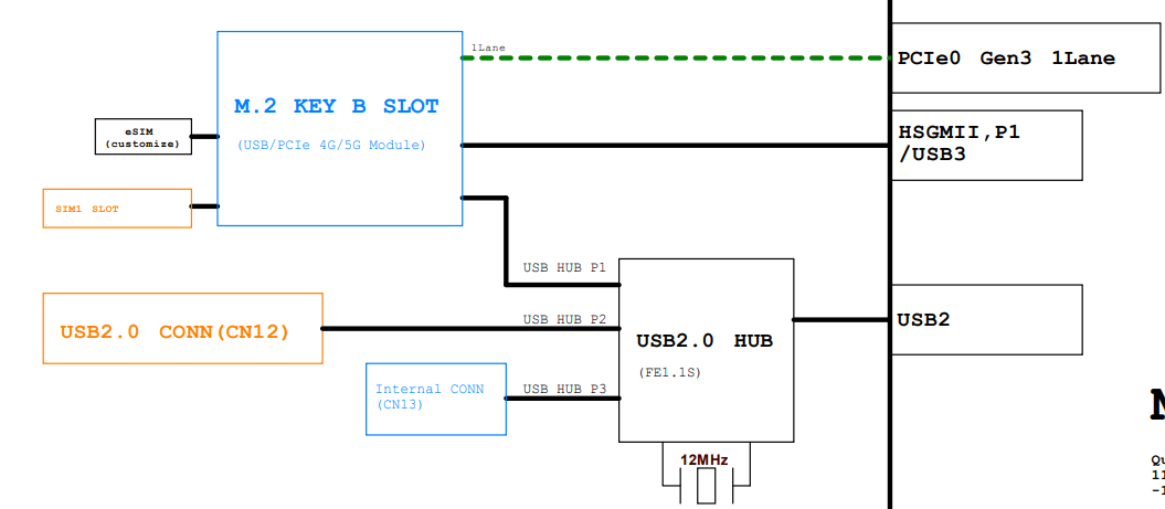
The BPI-R4Pro has one M.2 B-KEY slots, all for 4G/5G Cellular Modules.
it supports a pair of USB2.0 and USB3.0 signals, both extended via a USB 3.0 hub.
In addition, the CN8h have an additional PCIe3.0 1lane signal.
¶ NVMe SSD
The M.2 key Slot can only install one type of M.2 key module.
So the 4G/5G module and NvMe SSD can be installed only one.
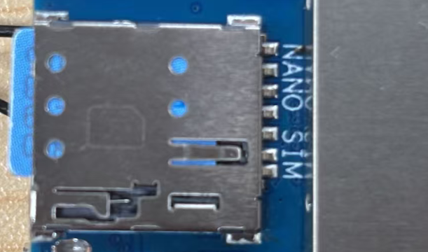
¶ NANO SimSlot
SIM1 can use the onboard NANO SIM Slot
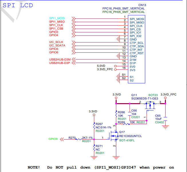
¶ FPC connector
It’s a 16pin conncetor.
It is usually used to connect spi lcd or i2c capacitive touch screen.
¶ Debug UART
The BPI-R4Mini has an onboard USB-to-UART chip(HT42B534-2), connected to the MT7988A’s Debug UART.
When connected USB Type-c connector(CN41) to PC, a USB-to-serial device will appear, which can be used for debugging.
Terminal setting : Baud=115200,Data bits: 8bit,Parity: none,Stop: 1bit, Flow control: none.
¶ eSIM
PIN42/44/46/48 of M.2 B-KEY Slot is the second set of SIM card signals.
NOTE : This requires your module to support it and this requires additional installtion of eSIM module.

¶ EEPROM
Built-in one EEPROM chip (P24C02A), can be used to store small amounts of data.
¶ Buttons
¶ LEDs
BPI-R4Mini has LEDs to indicate various operating states, including power, WiFi, Ethernet, 4G/5G cellular, etc
-
1x Power Green LED, Silkscreen "PWR" on the PCB,lights up when powered on and cannot be controlled by the software.
-
1x Status Blue LED,Silkscreen "B" on the PCB,Controlled by GPIO "PCA_A_IO1_6/SYS_LEDB".
-
2x WiFi Status Blue LEDs,The silk screen printing"W2G","W5G".
-
1x 5G cellular Status Blue LEDs,The silk screen
-
Each 2.5G RJ45 has two LEDs, and each 1G RJ45 has one LED to indicate the network status.
¶ DCIN
BPI-R4Pro requires a single +12V supply,and has multiple power supply , including DC power adapter, USB PD, POE, etc.
The supply voltage range is 9~24V, 12V or 20V is recommended, and it will automatically shut down when it exceeds 25.3V.
¶ DCIN(5521)
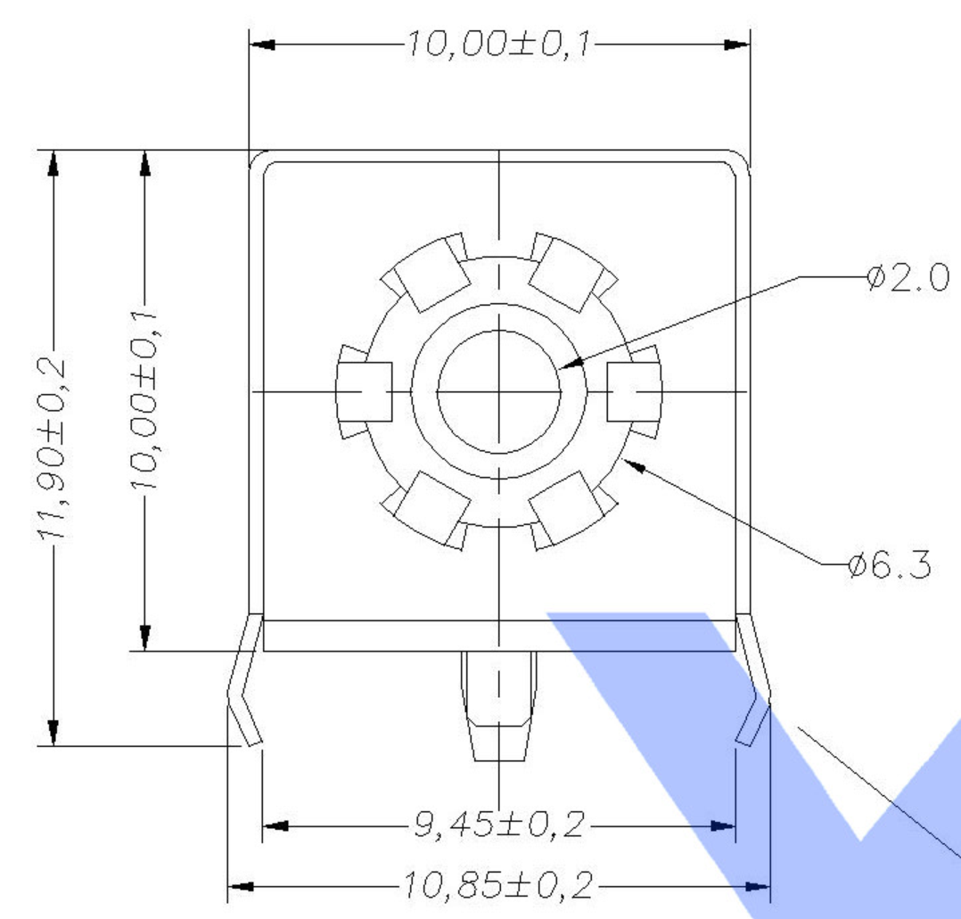
You can use a 12V/5A power adapter and plug it into the CN44 to power it. However, if other power supply exist at the same time, it will be switched to other power supply.
The dimensions of the CN44 slot are as follows(Inner Positive, Outer Negative):
¶ USB TypeC PD
The USB Type-C PD connector is connected to a CH224Q chip, which is used to communicate with the USB adapter and allow the adapter to output 20V voltage.
It is recommended to use a PD power supply that can output 20V and 65W or more.
¶ USB 2.0 connector
BPI-R4Mini has a USB2.0 Type-A connector that can be used to connect a USB flash drive or other USB devices.
The power output of the USB2.0 connector (CN12) is 5V/1300mA, which can be turned off via "PCA_A_IO1_3/VBUS_AB_PDN" output low.
¶ WIFI ANT
Thare are 3 ANT for WIFI.
¶ 4G/5G ANT
There are 3 ANTs for 4G.
There are 4 ANTs for 5G.
¶ Accessories
¶ 4G/5G Module
¶ M.2 4G/5G Module(USB Interface)
BPI-R4Mini supports M.2 USB Interface 4G LTE/5G Modules: Quectel EM05, RM500U-CN.
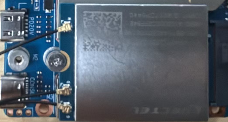
If you want to use M.2 Cellular Module on BPI-R4Mini:
-
Install 4G/5G Cellular Module into CN16 Slot(M.2 KEYB)
-
Inset NANOSIM Card into SIMSlot
-
Install antenna on the module
-
After powering on, it will automatically dial
| The availability of 4G/5G depends on the local carrier frequency band |

Quectel RM500U-CNV
Quectel RM520N-GL
root@OpenWrt:/# ifconfig usb0
usb0      Link encap:Ethernet  HWaddr 66:95:BC:F5:84:B3
          inet addr:10.1.58.8  Bcast:10.1.58.255  Mask:255.255.255.0
          inet6 addr: fe80::6495:bcff:fef5:84b3/64 Scope:Link
          inet6 addr: 2409:895a:30b6:738:6495:bcff:fef5:84b3/64 Scope:Global
          UP BROADCAST RUNNING MULTICAST  MTU:1500  Metric:1
          RX packets:587 errors:0 dropped:0 overruns:0 frame:0
          TX packets:867 errors:0 dropped:0 overruns:0 carrier:0
          collisions:0 txqueuelen:1000
          RX bytes:262208 (256.0 KiB)  TX bytes:200656 (195.9 KiB
root@OpenWrt:/# lsusb
Bus 001 Device 002: ID 1a86:8091  USB HUB
Bus 001 Device 001: ID 1d6b:0002 Linux 5.4.300 xhci-hcd xHCI Host Controller
Bus 002 Device 002: ID 2c7c:0900 Quectel RM500U-CNV
Bus 002 Device 001: ID 1d6b:0003 Linux 5.4.300 xhci-hcd xHCI Host Controller
root@OpenWrt:/#
root@OpenWrt:/# ping www.baidu.com
PING www.baidu.com (2409:8c54:870:310:0:ff:b0ed:40ac): 56 data bytes
64 bytes from 2409:8c54:870:310:0:ff:b0ed:40ac: seq=0 ttl=51 time=64.183 ms
64 bytes from 2409:8c54:870:310:0:ff:b0ed:40ac: seq=1 ttl=52 time=26.048 ms
64 bytes from 2409:8c54:870:310:0:ff:b0ed:40ac: seq=2 ttl=52 time=25.857 ms
64 bytes from 2409:8c54:870:310:0:ff:b0ed:40ac: seq=3 ttl=52 time=26.411 ms
64 bytes from 2409:8c54:870:310:0:ff:b0ed:40ac: seq=4 ttl=52 time=61.369 ms
64 bytes from 2409:8c54:870:310:0:ff:b0ed:40ac: seq=5 ttl=52 time=165.066 ms
64 bytes from 2409:8c54:870:310:0:ff:b0ed:40ac: seq=6 ttl=52 time=60.570 ms
64 bytes from 2409:8c54:870:310:0:ff:b0ed:40ac: seq=7 ttl=52 time=35.351 ms
^C
--- www.baidu.com ping statistics ---
8 packets transmitted, 8 packets received, 0% packet loss
round-trip min/avg/max = 25.857/58.106/165.066 ms
root@OpenWrt:/#EM05-CE
wwan0     Link encap:Ethernet  HWaddr 02:45:EC:8E:AD:80
          inet addr:10.7.83.4  Bcast:0.0.0.0  Mask:255.255.255.248
          inet6 addr: fe80::45:ecff:fe8e:ad80/64 Scope:Link
          UP BROADCAST RUNNING NOARP MULTICAST  MTU:1500  Metric:1
          RX packets:2 errors:0 dropped:0 overruns:0 frame:0
          TX packets:23 errors:0 dropped:0 overruns:0 carrier:0
          collisions:0 txqueuelen:1000
          RX bytes:236 (236.0 B)  TX bytes:3626 (3.5 KiB)

root@OpenWrt:/# lsusb
Bus 001 Device 013: ID 2c7c:0125 Quectel Incorporated LTE Module
Bus 002 Device 001: ID 1d6b:0003 Linux 5.4.300 xhci-hcd xHCI Host Controller
Bus 001 Device 002: ID 1a86:8091  USB HUB
Bus 001 Device 001: ID 1d6b:0002 Linux 5.4.300 xhci-hcd xHCI Host Controller
root@OpenWrt:/# ping www.baidu.com
PING www.baidu.com (111.45.11.5): 56 data bytes
64 bytes from 111.45.11.5: seq=0 ttl=52 time=80.437 ms
64 bytes from 111.45.11.5: seq=1 ttl=52 time=36.296 ms
64 bytes from 111.45.11.5: seq=2 ttl=53 time=41.240 ms
64 bytes from 111.45.11.5: seq=3 ttl=53 time=36.076 ms
64 bytes from 111.45.11.5: seq=4 ttl=53 time=41.002 ms
^C
--- www.baidu.com ping statistics ---
5 packets transmitted, 5 packets received, 0% packet loss
round-trip min/avg/max = 36.076/47.010/80.437 ms
root@OpenWrt:/#¶ M.2 4G/5G Module(PCIe Interface)
Theoretically, it also supports PCIe cellular modules, but it has not been tested
¶ Storage
¶ NVMe SSD
Please insert one M.2 NVMe SSD(PCI interface) into KeyB slot(CN8).
| No compatibility testing has been done and there is no guarantee that all SSDs can be used. |
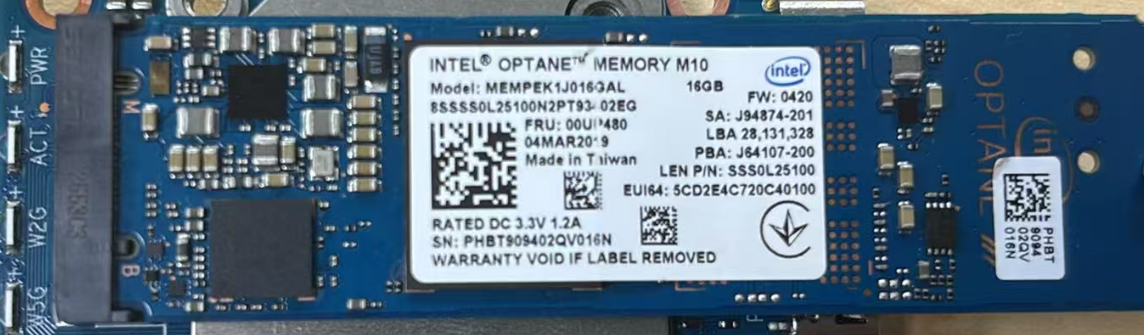
root@OpenWrt:/# lspci
0000:00:00.0 PCI bridge: MEDIATEK Corp. Device 7987 (rev 01)
0000:01:00.0 Non-Volatile memory controller: Intel Corporation NVMe Optane Memory Series
0001:00:00.0 PCI bridge: MEDIATEK Corp. Device 7987 (rev 01)
0001:01:00.0 Network controller: MEDIATEK Corp. Device 7993
root@OpenWrt:/# cat /proc/partitions
major minor  #blocks  name

 259        0   14065664 nvme0n1
 259        1   14063616 nvme0n1p1
 179        0    7634944 mmcblk0
 179        1        512 mmcblk0p1
 179        2       4096 mmcblk0p2
 179        3       2048 mmcblk0p3
 179        4      32768 mmcblk0p4
 179        5     262144 mmcblk0p5
  31        0       4608 mtdblock0
  31        1       4096 mtdblock1
  31        2       2048 mtdblock2
  31        3      32768 mtdblock3
  31        4    1048576 mtdblock4
  31        5     994880 mtdblock5
  31        6    2097152 mtdblock6
  31        7    4445696 mtdblock7
root@OpenWrt:/# ls /dev/nvm*
/dev/nvme0      /dev/nvme0n1    /dev/nvme0n1p1
root@OpenWrt:/# df -h
Filesystem                Size      Used Available Use% Mounted on
/dev/root                52.5M     52.5M         0 100% /rom
tmpfs                   997.4M    164.0K    997.2M   0% /tmp
/dev/mtdblock5          971.6M      5.6M    965.9M   1% /overlay
overlayfs:/overlay      971.6M      5.6M    965.9M   1% /
tmpfs                   512.0K         0    512.0K   0% /dev
root@OpenWrt:/mnt/nvme# mount /dev/nvme0n1p1 /mnt/nvme
root@OpenWrt:/mnt/nvme# df -h
Filesystem                Size      Used Available Use% Mounted on
/dev/root                52.5M     52.5M         0 100% /rom
tmpfs                   997.4M    164.0K    997.2M   0% /tmp
/dev/mtdblock5          971.6M      5.6M    965.9M   1% /overlay
overlayfs:/overlay      971.6M      5.6M    965.9M   1% /
tmpfs                   512.0K         0    512.0K   0% /dev
/dev/nvme0n1p1           13.4G     80.2M     13.3G   1% /mnt/nvme
root@OpenWrt:/mnt/nvme#¶ SPI NOR FLASH
¶ Heat sink
MTK OpwnWRT MP4.0 fan with PWM control reference.
root@OpenWrt:~# cat /sbin/fan-speed
#!/bin/sh /etc/rc.common

if [ ! -f /sys/class/pwm/pwmchip0/export ]; then
        exit 0
fi

### enable fan ###
echo 2 > /sys/class/pwm/pwmchip0/export
echo 10000 > /sys/class/pwm/pwmchip0/pwm2/period
echo 7000 >  /sys/class/pwm/pwmchip0/pwm2/duty_cycle
echo normal > /sys/class/pwm/pwmchip0/pwm2/polarity
echo 1 > /sys/class/pwm/pwmchip0/pwm2/enable

while :
do
        sleep 20
        result=`cat /sys/class/thermal/thermal_zone0/temp`

        temperature=$((result))
        #echo $temperature
        if [ ${temperature} -ge 53000 ]; then
                echo 7000 >  /sys/class/pwm/pwmchip0/pwm2/duty_cycle
        fi

        if [ ${temperature} -ge 62000 ]; then
                echo 10000 >  /sys/class/pwm/pwmchip0/pwm2/duty_cycle
        fi

        if [ ${temperature} -le 4800 ]; then
                echo 5000 >  /sys/class/pwm/pwmchip0/pwm2/duty_cycle
        fi

        if [ ${temperature} -le 4000 ]; then
                echo 3000 >  /sys/class/pwm/pwmchip0/pwm2/duty_cycle
        fi
done
root@OpenWrt:~#¶ PIN Definition
¶ FAN(CN4)
Details
| BPI-R4Mini FAN Connector PIN define | |
|---|---|
PIN No. |
Connection Destination |
1 |
5V |
2 |
GND |
3 |
PWM |
¶ M.2 Key B Slot(CN8)
Details
| BPI-R4Mini M.2 B-KEY Slot1(CN8) PIN define | |||
|---|---|---|---|
Connection Destination |
PIN No. |
PIN NO. |
Connection Destination |
NI |
1 |
2 |
VDD_BKEY_A |
GND |
3 |
4 |
VDD_BKEY_A |
GND |
5 |
6 |
NI(10K PullUp to 3.3V) |
USBHUB_USB1_Dp |
7 |
8 |
NI |
USBHUB_USB1_Dn |
9 |
10 |
BKEY-A-NET-STUn LED |
GND |
11 |
12 |
NOTCH |
NOTCH |
13 |
14 |
NOTCH |
NOTCH |
15 |
16 |
NOTCH |
NOTCH |
17 |
18 |
NOTCH |
NOTCH |
19 |
20 |
NI |
NI |
21 |
22 |
NI |
NI |
23 |
24 |
NI |
NI |
25 |
26 |
NI |
GND |
27 |
28 |
NI |
USBHUB_USB1_RXn |
29 |
30 |
USIM_RST-1A |
USBHUB_USB1_RXp |
31 |
32 |
USIM_CLK-1A |
GND |
33 |
34 |
USIM_DATA-1A |
USBHUB_USB1_TXn |
35 |
36 |
USIM_VDD-1A |
USBHUB_USB1_TXp |
37 |
38 |
NI |
GND |
39 |
40 |
NI |
PCIE_SW_A_C_RXn |
41 |
42 |
USIM_DATA-1B |
PCIE_SW_A_C_RXp |
43 |
44 |
USIM_CLK-1B |
GND |
45 |
46 |
USIM_RST-1B |
PCIE_SW_A_C_TXn |
47 |
48 |
USIM_VDD-1B |
PCIE_SW_A_C_TXp |
49 |
50 |
BKEY-A-PRESET_3P3V |
GND |
51 |
52 |
BKEY-A-CLKREQ_3P3V |
PCIE_SW_A_C_CKn |
53 |
54 |
BKEY-A-WAKE_3P3V |
PCIE_SW_A_C_CKp |
55 |
56 |
NI |
GND |
57 |
58 |
NI |
NI |
59 |
60 |
NI |
NI |
61 |
62 |
NI |
NI |
63 |
64 |
NI |
NI |
65 |
66 |
USIM_DET-1A |
BKEY-A-RST |
67 |
68 |
NI |
NI |
69 |
70 |
VDD_BKEY_A |
GND |
71 |
72 |
VDD_BKEY_A |
GND |
73 |
74 |
VDD_BKEY_A |
NI |
75 |
||
¶ FPC Connector(CN13)
Details
| BPI-R4Mini FPC Connector(CN13) PIN define | |||
|---|---|---|---|
Connection Destination |
PIN No. |
PIN NO. |
Connection Destination |
SPI_MOSI |
1 |
2 |
SPI_MISO |
SPI_CLK |
3 |
4 |
SPI_CS |
SPI_IO1 |
5 |
6 |
SPI_IO2 |
GND |
7 |
8 |
CTP_SCL |
CTP_SDA |
9 |
10 |
CTP_INT |
CTP_RST |
11 |
12 |
GND |
D1M |
13 |
14 |
D1P |
5V0 |
15 |
16 |
3V3 |
¶ DC-IN Connector(CN7)
Details
| BPI-R4mINI DCIN Connector(CN7) PIN define | |
|---|---|
PIN No. |
Connection Destination |
1 |
DCIN_12_24V |
2 |
GND |
¶ SPI NOR(CN15)
Details
| BPI-R4Mini SPI NOR(CN15) PIN define | |||
|---|---|---|---|
Connection Destination |
PIN No. |
PIN NO. |
Connection Destination |
SPI_MOSI |
1 |
2 |
BOOT_SEL2 |
SPI_MISO |
3 |
4 |
NOTCH |
SPI_CLK |
5 |
6 |
NOTCH |
SPI_CS |
7 |
8 |
NOTCH |
SPI_WP |
9 |
10 |
NOTCH |
SPI_HOLD |
11 |
12 |
NOTCH |
VCC33 |
13 |
14 |
DNU |
GND |
15 |
16 |
DNU |
NOR/NAND_CS_SEL |
17 |
18 |
DNU |
BOOT_SEL1 |
19 |
20 |
DNU |