¶ Overview
Banana Pi BPI-R4Pro Router board with MediaTek MT7988A (Filogic 880) quad-core ARM Corex-A73 design ,4GB/8GB DDR4 RAM,8GB eMMC,128MB SPI-NAND flash onboard, also have 2x 10Gbe SFP+, 4x Gbe network port,with USB3.2 port,M.2 support 4G/5G/NVME SSD.2x miniPCIe slots with PCIe3.0 2lane interface for Wi-Fi 7 NIC (Network Interface Card). It is a very high performance open source router development board.
| More Infomation: Banana Pi BPI-R4 Pro |
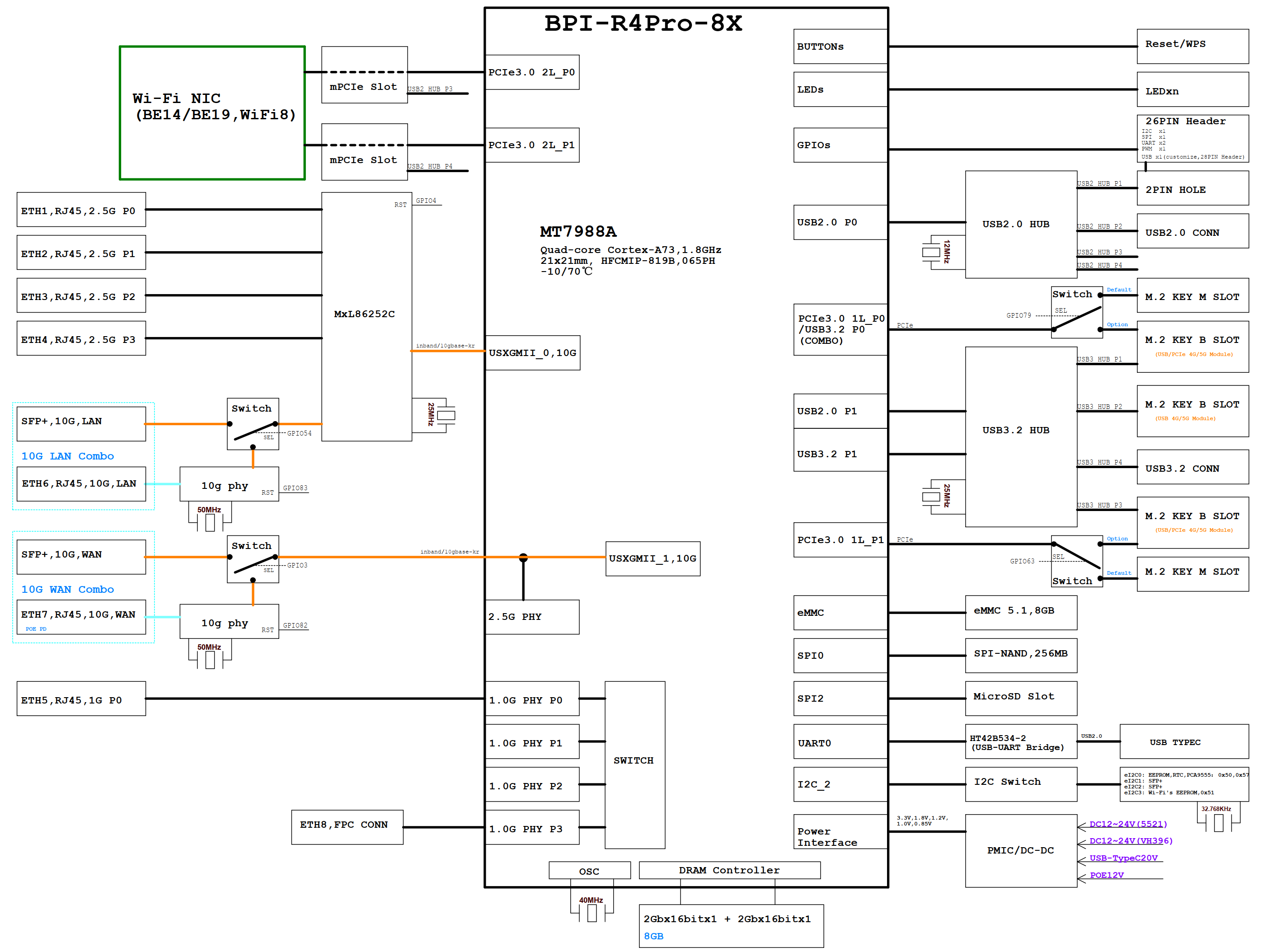
¶ Block Diagram(8X)
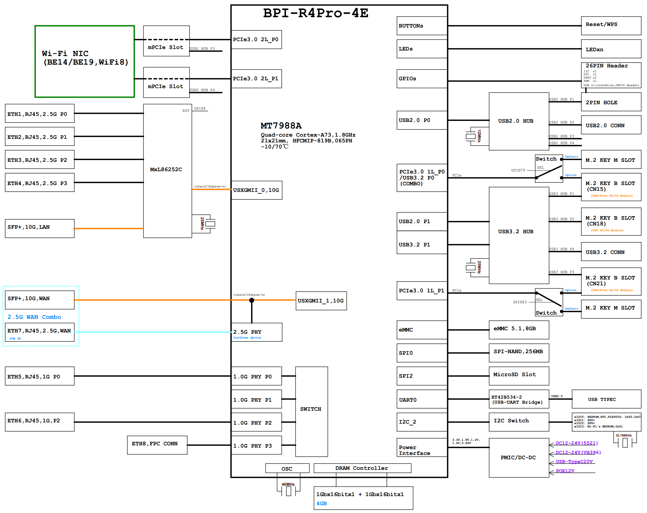
¶ Block Diagram(4e)
¶ Development
¶ Preparation
-
8G/above MicroSD card
-
MicroSD card Reader
-
USB Disk
-
USB TypeC cable
-
CAT6A Ethernet cable
-
12V/5A power adapter
(without any peripherals and network cable inset, the power consumption of BPI-R4Pro Main Board is about 10W, so 12V/2A will work.
But you need to determine whether you need a higher power power adapter according to your own accessory usage,12V/5A is recommended) -
Windows/Ubuntu System
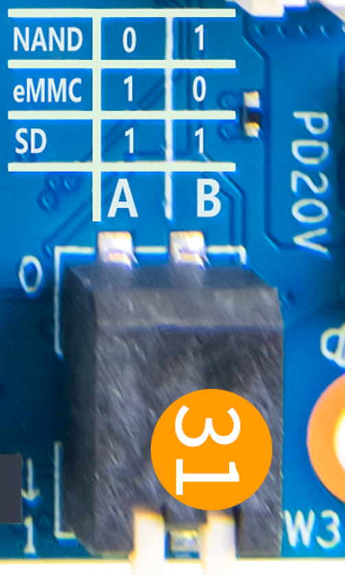
¶ BPI-R4Pro bootstrap setting
The tables below list the settings of the switch (SW3) and their functions.
-
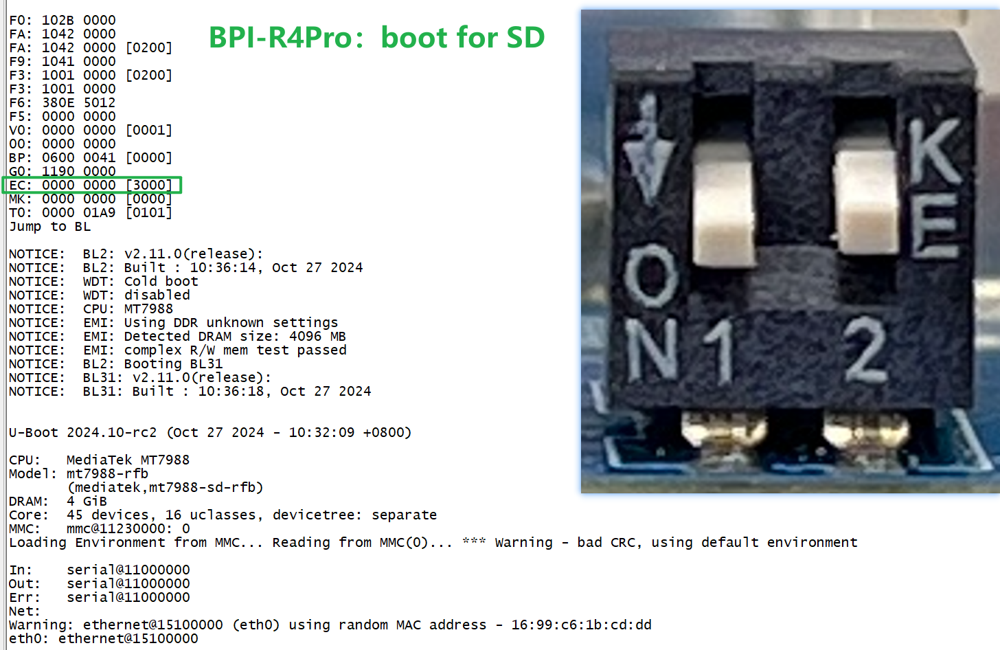
All Jumper is "1", BPI-R4Pro will boot from SD card
-
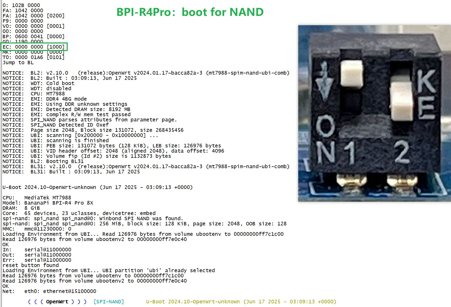
SW3-A is "0" and SW3-B is "1" , BPI-R4Pro will boot from SPI NAND
-
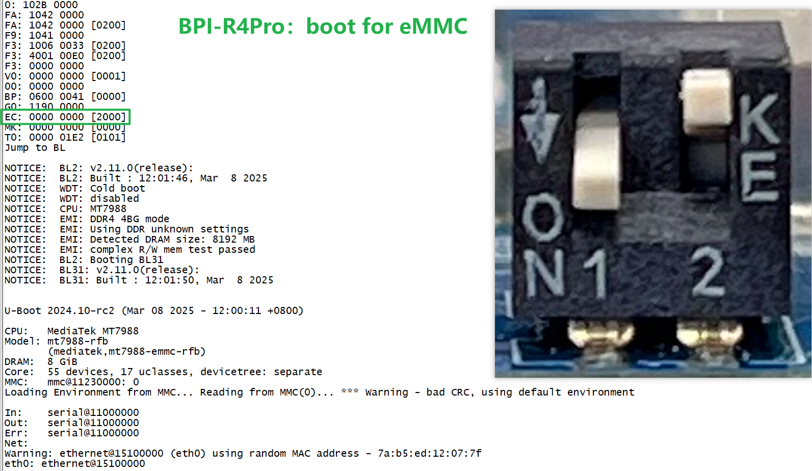
SW3-A is "1" and SW3-B is "0" , BPI-R4Pro will boot from eMMC
-
If the console said "system halt!", it means that the bootup storage does not cotain any OS
System halt!
¶ Flashing image
If you want to change the factory default system to another one,
Place Download the image file into a windows/ubuntu PC and follow the steps below.
¶ How to flash image to SD card
|
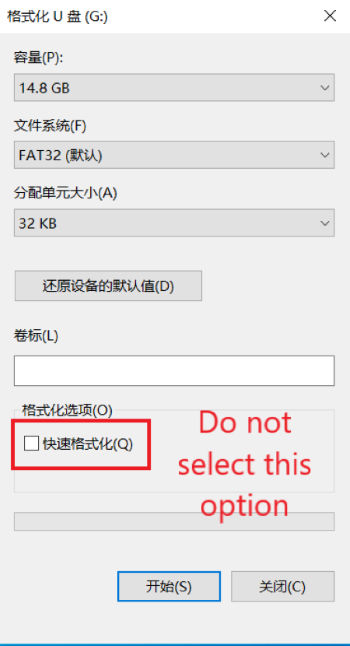
Please low level format the SD and clear all data of SD. It’s very important. Otherwise, you will encounter a "jffs2" error during the startup process. |
-
Please follow the following diagram for Windows PC.
-
Linux PC, you can use the "mksf" command for formatting, or use the "dd" command to write zeros.
Flash image to SD card on windows computer
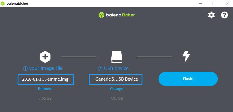
Balena Etcher is an opensource GUI flash tool by Balena, Flash OS images to SDcard or USB drive.
-
Click on "Flash from file" to select image.
-
Click on "Select target" to select USB device.
-
Click on "Flash!" Start flashing.
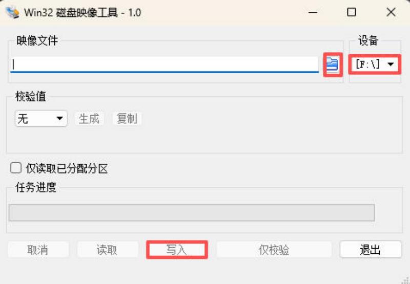
You can also use this tool for burning. win32diskimager
-
Click on "Image file" to select image.
-
Click on "Equipment" to select USB device.
-
Click on "Write down" Start flashing.
Flash image to SD card on linux computer
-
You could download latest image from our forum
-
Install bpi-tools on your Ubuntu. If you can’t access this URL or any other problems, please go to bpi-tools repo and install this tools manually.
apt-get install pv curl -sL https://github.com/BPI-SINOVOIP/bpi-tools/raw/master/bpi-tools | sudo -E bash -
After you download the image, insert your TF card into your Ubuntu. Execute
bpi-copy xxx.img /dev/sdxto install image on your MicroSD card
-
After step 3, then you can insert your MicroSD card into R4Pro,Change Bootstrap to boot from SD, and power power R4Pro.
¶ How to flash image to NAND Flash
| Factory image information:OpenWrt 24.10-SNAPSHOT Architecture:aarch64_cortex-a53 |
Before flashing image into Nand, please prepare a USB disk. Let’s take OpenWrt image (BPI-R4Pro-8X-BE14-MT76-OpenWRT24.10-DSA-snand-251120.bin) for example, the steps are below:
-
Format the USB disk to FAT32.
-
Copy Nand boot OpenWrt image(BPI-R4Pro-8X-BE14-MT76-OpenWRT24.10-DSA-snand-251120.bin) to USB disk.
-
Change the bootstrap to sd or eMMC boot, then power up the board.
-
Plug in USB disk to the board, and mount the USB to /mnt or other directory as follows: (you can skip mounting if it is mounted automatically)
mount -t vfat /dev/sda1 /mnt cd /mnt -
Execute following command to erase the whole Nand flash and copy image to nand device:
The BPI-R4Pro’s NAND image is flashed to MTD3 (unlike the BPI-R4, which is flashed to MTD0). cat /proc/mtd dev: size erasesize name mtd0: 00200000 00020000 "bl2" mtd1: 00400000 00020000 "Factory" mtd2: 0fa00000 00020000 "ubi" mtd3: 10000000 00020000 "nand" mtd erase /dev/mtd3 mtd write BPI-R4Pro-8X-BE14-MT76-OpenWRT24.10-DSA-snand-251120.bin /dev/mtd3 -
Power off BPI-R4Po, remove u-disk driver, change bootstrap to nand boot and power up again.
¶ How to flash image to eMMC
| Because SD card and EMMC device share one SOC’s controller, it is necessary to switch to NAND startup and then burn the EMMC image into the EMMC. Finally, you will change the boot to boot from EMMC. |
Let’s take OpenWrt image (bl2_emmc-r4pro.img, mtk-bpi-r4pro-EMMC-20250928.img) for example, the steps are below:
-
Format the USB disk to FAT32.
-
Copy EMMC boot OpenWrt image(bl2_emmc-r4pro.img, mtk-bpi-r4pro-EMMC-20250928.img) to USB disk,
if the image is compressed please uncompress it before copying to USB disk. -
Change the bootstrap to Nand boot and poewer up R4Pro.
-
Plug in USB disk to the board, and mount the USB to /mnt or other directory as follows: (you can skip mounting if it is mounted automatically)
mount -t vfat /dev/sda1 /mnt cd /mnt -
Execute :
echo 0 > /sys/block/mmcblk0boot0/force_ro dd if=bl2_emmc-r4pro.img of=/dev/mmcblk0boot0 dd if=mtk-bpi-r4pro-EMMC-20250928.img of=/dev/mmcblk0 mmc bootpart enable 1 1 /dev/mmcblk0 -
Power off BPI-R4Pro, remove u-disk driver, change bootstrap to emmc boot and power up again.
¶ Power ON
-
Using your USB TypeC cable Connect to debug console(CN41) on BPI-R4Pro
-
Install Terminal Emulator or use a serial terminal that you are familiar with,
change the setting as follows: Baud=115200,Data bits: 8bit,Parity: none,Stop: 1bit, Flow control: none; -
Set up the bootstrap before supplying power,
(If you are using BPI-R4Pro for the first time, it is recommended to set it to NAND boot) -
when Connect power adapter to DC-IN connector(CN44),Green LED “PWR” light up,
And there will be characters similar to the following on the console.
This means you have successfully started BPI-R4Pro.
Details
F0: 102B 0000
FA: 1042 0000
FA: 1042 0000 [0200]
F9: 0000 0000
V0: 0000 0000 [0001]
00: 0000 0000
BP: 0600 0041 [0000]
G0: 1190 0000
EC: 0000 0000 [1000]
MK: 0000 0000 [0000]
T0: 0000 01A6 [0101]
Jump to BL

NOTICE:  BL2: v2.10.0   (release):OpenWrt v2024.01.17~bacca82a-3 (mt7988-spim-nand-ubi-comb)
NOTICE:  BL2: Built : 03:09:13, Jun 17 2025
NOTICE:  WDT: Cold boot
NOTICE:  WDT: disabled
NOTICE:  CPU: MT7988
NOTICE:  EMI: DDR4 4BG mode
NOTICE:  EMI: Using DDR unknown settings
NOTICE:  EMI: Detected DRAM size: 8192 MB
NOTICE:  EMI: complex R/W mem test passed
NOTICE:  SPI_NAND parses attributes from parameter page.
NOTICE:  SPI_NAND Detected ID 0xef
NOTICE:  Page size 2048, Block size 131072, size 268435456
NOTICE:  UBI: scanning [0x200000 - 0x10000000] ...
NOTICE:  UBI: Bad EC magic in block 1904 4e4d4d31
NOTICE:  UBI: Bad EC magic in block 1905 ffffffff
NOTICE:  UBI: Bad EC magic in block 1906 ffffffff
NOTICE:  UBI: Bad EC magic in block 1907 4e4d4d31
NOTICE:  UBI: Bad VID magic in block 2031 4e4d4d30
NOTICE:  UBI: scanning is finished
NOTICE:  UBI: PEB size: 131072 bytes (128 KiB), LEB size: 126976 bytes
NOTICE:  UBI: VID header offset: 2048 (aligned 2048), data offset: 4096
NOTICE:  UBI: Volume fip (Id #2) size is 1132873 bytes
NOTICE:  BL2: Booting BL31
NOTICE:  BL31: v2.10.0  (release):OpenWrt v2024.01.17~bacca82a-3 (mt7988-spim-nand-ubi-comb)
NOTICE:  BL31: Built : 03:09:13, Jun 17 2025


U-Boot 2024.10-OpenWrt-unknown (Jun 17 2025 - 03:09:13 +0000)

CPU:   MediaTek MT7988
Model: BananaPi BPI-R4 Pro 8X
DRAM:  8 GiB
Core:  65 devices, 23 uclasses, devicetree: embed
spi-nand: spi_nand spi_nand@0: Winbond SPI NAND was found.
spi-nand: spi_nand spi_nand@0: 256 MiB, block size: 128 KiB, page size: 2048, OOB size: 128
MMC:   mmc@11230000: 0
Loading Environment from UBI... Read 126976 bytes from volume ubootenv to 00000000ff7c1c00
Read 126976 bytes from volume ubootenv2 to 00000000ff7e0c40¶ Interfaces
¶ R4Pro 4E switchable combo network port
First, you need to enter the uboot interface, which can be done by pressing Esc in the ubootmenu.
¶ Switch to 10G SFP WAN port
You can switch network ports by entering the command below
MT7988> printenv
MT7988> setenv bootconf_extra mt7988a-bananapi-bpi-r4-pro-4e-sfp
MT7988> saveenv

Saving Environment to UBI... UBI partition 'ubi' already selected
Writing to UBI... done
OK

MT7988> reset¶ Switch to 2.5G RJ45 WAN port
You can switch network ports by entering the command below
MT7988> printenv
MT7988> setenv bootconf_extra mt7988a-bananapi-bpi-r4-pro-4e-iphy
MT7988> saveenv

Saving Environment to UBI... UBI partition 'ubi' already selected
Writing to UBI... done
OK

MT7988> reset¶ 10G Ethernet
MT7988A has two USXGMIIs for 10G ethernet, of which USXGMII Port1 is used as a WAN port (10G SFP+ WAN/10G RJ45 WAN), USXGMII Port0 is connected to USXGMII0 of Switch MxL86252C, and USXGMII1 of MxL86252C is used as a LAN port (10G SFP+ LAN/10G RJ45 LAN)
The SFP serdes speed of BPI-R4Pro is fixed at 10Gbps, so only SFP that support this can be used!
Tested 10G SFP+ Copper/Fibre Module
¶ 10G WAN
¶ Block Diagram
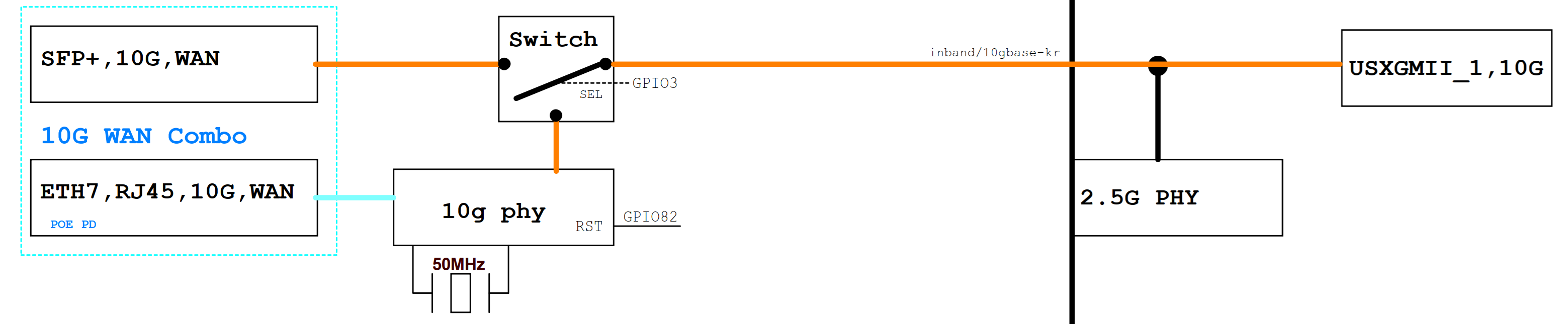
¶ 10G SFP+ WAN
When MT7988A’s GPIO3 ouput=High, USXGMII Port1 switches to SFP+ WAN Port.
At this time, 10G SFP+ WAN is functional, but 10G RJ45 WAN will be ineffective.
Now, you can insert a 10G SFP+ Copper/Fibre Module to get a 10G network interface.
Or you can also insert a 10G XGSPON Stick to access the Telecom operator’s network.
|
Our default image configuration: After inserting the SFP module, USXGMII will automatically switch to 10G SFP+, and 10G RJ45 will not be usable; Therefore, if you want to use 10G RJ45, Do NOT insert any module on SFP+. |
Details
root@R4Pro-01i-NAND:~#
[   84.886999] sfp sfp2: SM: enter empty:down:down event insert
[   84.892666] sfp sfp2: SM: exit probe:down:down
[   85.185321] mtk_soc_eth 15100000.ethernet: ethernet mux: switch to channel1
[   85.192285] mtk_soc_eth 15100000.ethernet eth1: configuring for inband/10gbase-r link mode
[   85.211253] sfp sfp2: SM: enter probe:down:down event dev_up
[   85.216906] sfp sfp2: SM: exit probe:up:down
[   85.221181] sfp sfp2: SM: enter probe:up:down event timeout
[   85.237792] sfp sfp2: module OEM              SFP-10G-T        rev 10   sn 2309250002       dc 230925
[   85.247181] sfp sfp2: module OEM              SFP-10G-T        rev 10   has been found in the quirk list
[   85.256652] sfp sfp2: sfp: support mode 00,00000000,00000800,00007040
[   85.263083] sfp sfp2: tx disable 1 -> 0
[   85.266923] sfp sfp2: SM: exit present:up:wait
[   85.286250] hwmon hwmon1: temp1_input not attached to any thermal zone
[   85.325328] sfp sfp2: SM: enter present:up:wait event timeout
[   85.331066] sfp sfp2: probing phy device through the [MDIO_I2C_ROLLBALL] protocol
[   86.437671] hwmon hwmon2: temp1_input not attached to any thermal zone
[   87.407412] sfp sfp2: CL45 PHY device [0x31c3:0x1c13] found!
[   87.413081] sfp sfp2: CL45 PHY device [0x31c3:0x1c13] found!
[   87.418744] sfp sfp2: CL45 PHY device [0x31c3:0x1c13] found!
[   87.424392] sfp sfp2: CL45 PHY device [0x31c3:0x1c13] found!
[   87.430044] sfp sfp2: CL45 PHY device [0x31c3:0x1c13] found!
[   87.435697] sfp sfp2: CL45 PHY device [0x31c3:0x1c13] found!
[   87.441344] sfp sfp2: CL45 PHY device [0x0000:0x0000] found!
[   87.446992] sfp sfp2: CL45 PHY driver [Aquantia AQR113C] found!
[   87.452899] sfp sfp2: phy: support mode 00,00000000,00018000,000e706c
[   87.459339] mtk_soc_eth 15100000.ethernet eth1: requesting link mode inband/10gbase-r with support 00,00000000,00018000,000e706c
[   88.677484] mtk_soc_eth 15100000.ethernet eth1: PHY [i2c:sfp2:11] driver [Aquantia AQR113C] (irq=POLL)
[   88.767362] sfp sfp2: SM: exit present:up:link_up
[   88.772542] sfp sfp2: SM: enter present:up:link_up event los_high
[   88.793265] mtk_soc_eth 15100000.ethernet eth1: resolve link status: system iface=0, line iface=0
[   88.802137] sfp sfp2: SM: exit present:up:wait_los
[   93.766046] sfp sfp2: SM: enter present:up:wait_los event los_low
[   93.772150] sfp sfp2: SM: exit present:up:link_up
[   93.772161] mtk_soc_eth 15100000.ethernet eth1: resolve link status: system iface=1, line iface=0
[   94.795333] mtk_soc_eth 15100000.ethernet eth1: resolve link status: system iface=1, line iface=0
[   95.480326] mtk_soc_eth 15100000.ethernet eth1: Link is Up - 10Gbps/Full - flow control off
[   95.480351] br-wan: port 1(eth1) entered blocking state
[   95.493886] br-wan: port 1(eth1) entered forwarding state
[  100.489488] br-wan: entered allmulticast mode
[  100.493951] br-lan: entered allmulticast mode

root@R4Pro-01i-NAND:~#
root@R4Pro-01i-NAND:~#
root@R4Pro-01i-NAND:~# ethtool eth1
Settings for eth1:
        Supported ports: [  ]
        Supported link modes:   100baseT/Full
                                1000baseT/Full
                                10000baseT/Full
                                1000baseKX/Full
                                10000baseKX4/Full
                                10000baseKR/Full
                                2500baseT/Full
                                5000baseT/Full
        Supported pause frame use: Symmetric Receive-only
        Supports auto-negotiation: Yes
        Supported FEC modes: Not reported
        Advertised link modes:  100baseT/Full
                                1000baseT/Full
                                10000baseT/Full
                                1000baseKX/Full
                                10000baseKX4/Full
                                10000baseKR/Full
                                2500baseT/Full
                                5000baseT/Full
        Advertised pause frame use: Symmetric Receive-only
        Advertised auto-negotiation: Yes
        Advertised FEC modes: Not reported
        Link partner advertised link modes:  10baseT/Half 10baseT/Full
                                             100baseT/Half 100baseT/Full
                                             1000baseT/Half 1000baseT/Full
                                             10000baseT/Full
                                             2500baseT/Full
                                             5000baseT/Full
        Link partner advertised pause frame use: No
        Link partner advertised auto-negotiation: Yes
        Link partner advertised FEC modes: Not reported
        Speed: 10000Mb/s
        Duplex: Full
        Auto-negotiation: on
        Port: Twisted Pair
        PHYAD: 11
        Transceiver: external
        MDI-X: Unknown
        Current message level: 0x000000ff (255)
                               drv probe link timer ifdown ifup rx_err tx_err
        Link detected: yes
root@R4Pro-01i-NAND:~#
root@R4Pro-01i-NAND:~#
root@R4Pro-01i-NAND:~# i2cdetect -y 5
     0  1  2  3  4  5  6  7  8  9  a  b  c  d  e  f
00:                         -- -- -- -- -- -- -- --
10: -- -- -- -- -- -- -- -- -- -- -- -- -- -- -- --
20: -- -- -- -- -- -- -- -- -- -- -- -- -- -- -- --
30: -- -- -- -- -- -- -- -- -- -- -- -- -- -- -- --
40: -- -- -- -- -- -- -- -- -- -- -- -- -- -- -- --
50: 50 51 -- -- -- -- 56 -- -- -- -- -- -- -- -- --
60: -- -- -- -- -- -- -- -- -- -- -- -- -- -- -- --
70: UU -- -- -- -- -- -- --
root@R4Pro-01i-NAND:~#¶ 10G RJ45 WAN(Only available on 8X)
On the other hand, when MT7988A’s GPIO3 ouput=Low, USXGMII Port1 switches to 10G RJ45 WAN Port.
You need to load the 10G PHY AS21010P’s driver to make the 10G RJ45 LAN work.
At this time, 10G RJ45 WAN is functional, but 10G SFP+ WAN will be ineffective.
|
The power consumption of AS21010P is very high,a good heat dissipation effect heat sink must be used. |
Details
root@R4Pro-01i-NAND:~# ethtool eth1
Settings for eth1:
        Supported ports: [ TP    MII ]
        Supported link modes:   100baseT/Full
                                1000baseT/Half 1000baseT/Full
                                10000baseT/Full
                                2500baseT/Full
                                5000baseT/Full
        Supported pause frame use: Symmetric Receive-only
        Supports auto-negotiation: Yes
        Supported FEC modes: Not reported
        Advertised link modes:  100baseT/Full
                                1000baseT/Half 1000baseT/Full
                                10000baseT/Full
                                2500baseT/Full
                                5000baseT/Full
        Advertised pause frame use: Symmetric Receive-only
        Advertised auto-negotiation: Yes
        Advertised FEC modes: Not reported
        Link partner advertised link modes:  10baseT/Half 10baseT/Full
                                             100baseT/Half 100baseT/Full
                                             1000baseT/Half 1000baseT/Full
        Link partner advertised pause frame use: No
        Link partner advertised auto-negotiation: Yes
        Link partner advertised FEC modes: Not reported
        Speed: 10000Mb/s
        Duplex: Full
        Auto-negotiation: on
        Port: Twisted Pair
        PHYAD: 1c
        Transceiver: external
        MDI-X: Unknown
        Current message level: 0x000000ff (255)
                               drv probe link timer ifdown ifup rx_err tx_err
        Link detected: yes
root@R4Pro-01i-NAND:~#¶ 10G LAN
¶ Block Diagram
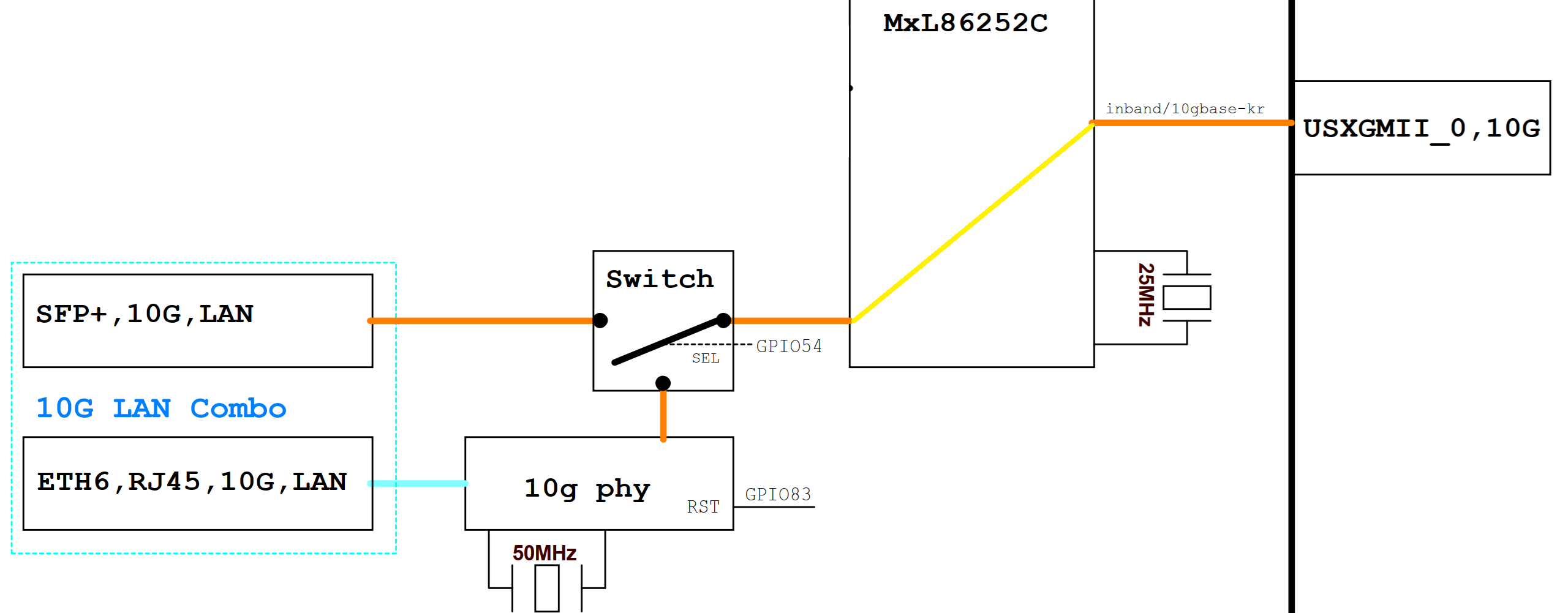
¶ 10G SFP+ LAN
When MT7988A’s GPIO54 ouput=Low, MxL86252C’s USXGMII1 switches to 10G SFP+ LAN Port.
At this time, 10G SFP+ LAN is functional, but 10G RJ45 LAN will be ineffective.
Now, you can insert a 10G SFP+ Copper/Fibre Module to get a 10G network interface.
|
Our default image configuration: After inserting the SFP module, USXGMII will automatically switch to 10G SFP+, and 10G RJ45 will not be usable; Therefore, if you want to use 10G RJ45, Do NOT insert any module on SFP+. |
¶ 10G RJ45 LAN(Only available on 8X)
On the other hand, when MT7988A’s GPIO54 ouput=High,MxL86252C’s USXGMII1 switches to 10G RJ45 WAN Port.
You need to load the 10G PHY AS21010P’s driver to make the 10G RJ45 LAN work.
At this time, 10G RJ45 LAN is functional, but 10G SFP+ LAN will be ineffective.
|
The power consumption of AS21010P is very high,a good heat dissipation effect heat sink must be used. |
¶ 10G iperf3 test
-
PC1 ←(10G LAN) BPI-R4Pro (10G WAN)→PC2
Details
xiao@FN-NUC5:~$ iperf3 -c 10.0.1.12 -t 30 -i 30
Connecting to host 10.0.1.12, port 5201
[  5] local 10.0.11.233 port 50470 connected to 10.0.1.12 port 5201
[ ID] Interval           Transfer     Bitrate         Retr  Cwnd
[  5]   0.00-30.00  sec  32.8 GBytes  9.40 Gbits/sec  1043   2.28 MBytes
- - - - - - - - - - - - - - - - - - - - - - - - -
[ ID] Interval           Transfer     Bitrate         Retr
[  5]   0.00-30.00  sec  32.8 GBytes  9.40 Gbits/sec  1043             sender
[  5]   0.00-30.00  sec  32.8 GBytes  9.40 Gbits/sec                  receiver

iperf Done.
xiao@FN-NUC5:~$ iperf3 -c 10.0.1.12 -t 30 -i 30 -R
Connecting to host 10.0.1.12, port 5201
Reverse mode, remote host 10.0.1.12 is sending
[  5] local 10.0.11.233 port 44756 connected to 10.0.1.12 port 5201
[ ID] Interval           Transfer     Bitrate         Retr  Cwnd
[  5]   0.00-30.00  sec  32.8 GBytes  9.40 Gbits/sec
- - - - - - - - - - - - - - - - - - - - - - - - -
[ ID] Interval           Transfer     Bitrate         Retr
[  5]   0.00-30.00  sec  32.8 GBytes  9.40 Gbits/sec  111             sender
[  5]   0.00-30.00  sec  32.8 GBytes  9.40 Gbits/sec                  receiver

iperf Done.
xiao@FN-NUC5:~$-
PC1 ← →(10G LAN) BPI-R4Pro
Details
xiao@FN-NUC5:~$ iperf3 -c 10.0.11.1 -t 30 -i 30
Connecting to host 10.0.11.1, port 5201
[  5] local 10.0.11.233 port 56126 connected to 10.0.11.1 port 5201
[ ID] Interval           Transfer     Bitrate         Retr  Cwnd
[  5]   0.00-30.00  sec  22.0 GBytes  6.31 Gbits/sec    2   3.14 MBytes
- - - - - - - - - - - - - - - - - - - - - - - - -
[ ID] Interval           Transfer     Bitrate         Retr
[  5]   0.00-30.00  sec  22.0 GBytes  6.31 Gbits/sec    2             sender
[  5]   0.00-30.00  sec  22.0 GBytes  6.30 Gbits/sec                  receiver

iperf Done.
xiao@FN-NUC5:~$
xiao@FN-NUC5:~$ iperf3 -c 10.0.11.1 -t 30 -i 30 -P 5
Connecting to host 10.0.11.1, port 5201
[  5] local 10.0.11.233 port 46330 connected to 10.0.11.1 port 5201
[  7] local 10.0.11.233 port 46346 connected to 10.0.11.1 port 5201
[  9] local 10.0.11.233 port 46360 connected to 10.0.11.1 port 5201
[ 11] local 10.0.11.233 port 46366 connected to 10.0.11.1 port 5201
[ 13] local 10.0.11.233 port 46368 connected to 10.0.11.1 port 5201
[ ID] Interval           Transfer     Bitrate         Retr  Cwnd
[  5]   0.00-30.00  sec  6.99 GBytes  2.00 Gbits/sec    0   3.87 MBytes
[  7]   0.00-30.00  sec  7.06 GBytes  2.02 Gbits/sec    0   2.41 MBytes
[  9]   0.00-30.00  sec  8.00 GBytes  2.29 Gbits/sec    0   3.38 MBytes
[ 11]   0.00-30.00  sec  5.29 GBytes  1.51 Gbits/sec    0   2.06 MBytes
[ 13]   0.00-30.00  sec  5.60 GBytes  1.60 Gbits/sec    0   2.65 MBytes
[SUM]   0.00-30.00  sec  32.9 GBytes  9.43 Gbits/sec    0
- - - - - - - - - - - - - - - - - - - - - - - - -
[ ID] Interval           Transfer     Bitrate         Retr
[  5]   0.00-30.00  sec  6.99 GBytes  2.00 Gbits/sec    0             sender
[  5]   0.00-30.00  sec  6.98 GBytes  2.00 Gbits/sec                  receiver
[  7]   0.00-30.00  sec  7.06 GBytes  2.02 Gbits/sec    0             sender
[  7]   0.00-30.00  sec  7.05 GBytes  2.02 Gbits/sec                  receiver
[  9]   0.00-30.00  sec  8.00 GBytes  2.29 Gbits/sec    0             sender
[  9]   0.00-30.00  sec  7.98 GBytes  2.29 Gbits/sec                  receiver
[ 11]   0.00-30.00  sec  5.29 GBytes  1.51 Gbits/sec    0             sender
[ 11]   0.00-30.00  sec  5.28 GBytes  1.51 Gbits/sec                  receiver
[ 13]   0.00-30.00  sec  5.60 GBytes  1.60 Gbits/sec    0             sender
[ 13]   0.00-30.00  sec  5.59 GBytes  1.60 Gbits/sec                  receiver
[SUM]   0.00-30.00  sec  32.9 GBytes  9.43 Gbits/sec    0             sender
[SUM]   0.00-30.00  sec  32.9 GBytes  9.41 Gbits/sec                  receiver

iperf Done.
xiao@FN-NUC5:~$
xiao@FN-NUC5:~$ iperf3 -c 10.0.11.1 -t 30 -i 30 -R
Connecting to host 10.0.11.1, port 5201
Reverse mode, remote host 10.0.11.1 is sending
[  5] local 10.0.11.233 port 36980 connected to 10.0.11.1 port 5201
[ ID] Interval           Transfer     Bitrate         Retr  Cwnd
[  5]   0.00-30.00  sec  32.9 GBytes  9.41 Gbits/sec
- - - - - - - - - - - - - - - - - - - - - - - - -
[ ID] Interval           Transfer     Bitrate         Retr
[  5]   0.00-30.00  sec  32.9 GBytes  9.41 Gbits/sec  125             sender
[  5]   0.00-30.00  sec  32.9 GBytes  9.41 Gbits/sec                  receiver

iperf Done.
xiao@FN-NUC5:~$-
BPI-R4Pro (10G WAN)← →PC2
Details
root@R4Pro-01i-NAND:~# iperf3 -c 10.0.1.12 -t 30 -i 30
Connecting to host 10.0.1.12, port 5201
[  5] local 10.0.1.16 port 42746 connected to 10.0.1.12 port 5201
[ ID] Interval           Transfer     Bitrate         Retr  Cwnd
[  5]   0.00-30.02  sec  32.9 GBytes  9.41 Gbits/sec   41   3.40 MBytes
- - - - - - - - - - - - - - - - - - - - - - - - -
[ ID] Interval           Transfer     Bitrate         Retr
[  5]   0.00-30.02  sec  32.9 GBytes  9.41 Gbits/sec   41             sender
[  5]   0.00-30.02  sec  32.9 GBytes  9.41 Gbits/sec                  receiver

iperf Done.
root@R4Pro-01i-NAND:~#
root@R4Pro-01i-NAND:~# iperf3 -c 10.0.1.12 -t 30 -i 30 -R
Connecting to host 10.0.1.12, port 5201
Reverse mode, remote host 10.0.1.12 is sending
[  5] local 10.0.1.16 port 60504 connected to 10.0.1.12 port 5201
[ ID] Interval           Transfer     Bitrate         Retr  Cwnd
[  5]   0.00-30.03  sec  21.5 GBytes  6.16 Gbits/sec
- - - - - - - - - - - - - - - - - - - - - - - - -
[ ID] Interval           Transfer     Bitrate         Retr
[  5]   0.00-30.03  sec  21.5 GBytes  6.16 Gbits/sec  558             sender
[  5]   0.00-30.03  sec  21.5 GBytes  6.16 Gbits/sec                  receiver

iperf Done.
root@R4Pro-01i-NAND:~#
root@R4Pro-01i-NAND:~# iperf3 -c 10.0.1.12 -t 30 -i 30 -R -P 5
Connecting to host 10.0.1.12, port 5201
Reverse mode, remote host 10.0.1.12 is sending
[  5] local 10.0.1.16 port 49938 connected to 10.0.1.12 port 5201
[  7] local 10.0.1.16 port 49950 connected to 10.0.1.12 port 5201
[  9] local 10.0.1.16 port 49958 connected to 10.0.1.12 port 5201
[ 11] local 10.0.1.16 port 49974 connected to 10.0.1.12 port 5201
[ 13] local 10.0.1.16 port 49976 connected to 10.0.1.12 port 5201
[ ID] Interval           Transfer     Bitrate         Retr  Cwnd
[  5]   0.00-30.02  sec  8.66 GBytes  2.48 Gbits/sec
[  7]   0.00-30.02  sec  5.39 GBytes  1.54 Gbits/sec
[  9]   0.00-30.02  sec  5.57 GBytes  1.59 Gbits/sec
[ 11]   0.00-30.03  sec  7.81 GBytes  2.23 Gbits/sec
[ 13]   0.00-30.03  sec  5.41 GBytes  1.55 Gbits/sec
[SUM]   0.00-30.02  sec  32.8 GBytes  9.39 Gbits/sec
- - - - - - - - - - - - - - - - - - - - - - - - -
[ ID] Interval           Transfer     Bitrate         Retr
[  5]   0.00-30.03  sec  8.66 GBytes  2.48 Gbits/sec  2641             sender
[  5]   0.00-30.02  sec  8.66 GBytes  2.48 Gbits/sec                  receiver
[  7]   0.00-30.03  sec  5.39 GBytes  1.54 Gbits/sec  1541             sender
[  7]   0.00-30.02  sec  5.39 GBytes  1.54 Gbits/sec                  receiver
[  9]   0.00-30.03  sec  5.57 GBytes  1.59 Gbits/sec  2280             sender
[  9]   0.00-30.02  sec  5.57 GBytes  1.59 Gbits/sec                  receiver
[ 11]   0.00-30.03  sec  7.81 GBytes  2.23 Gbits/sec  3222             sender
[ 11]   0.00-30.02  sec  7.81 GBytes  2.23 Gbits/sec                  receiver
[ 13]   0.00-30.03  sec  5.41 GBytes  1.55 Gbits/sec  1766             sender
[ 13]   0.00-30.02  sec  5.41 GBytes  1.55 Gbits/sec                  receiver
[SUM]   0.00-30.03  sec  32.9 GBytes  9.40 Gbits/sec  11450             sender
[SUM]   0.00-30.02  sec  32.8 GBytes  9.39 Gbits/sec                  receiver

iperf Done.
root@R4Pro-01i-NAND:~#¶ 2.5G RJ45
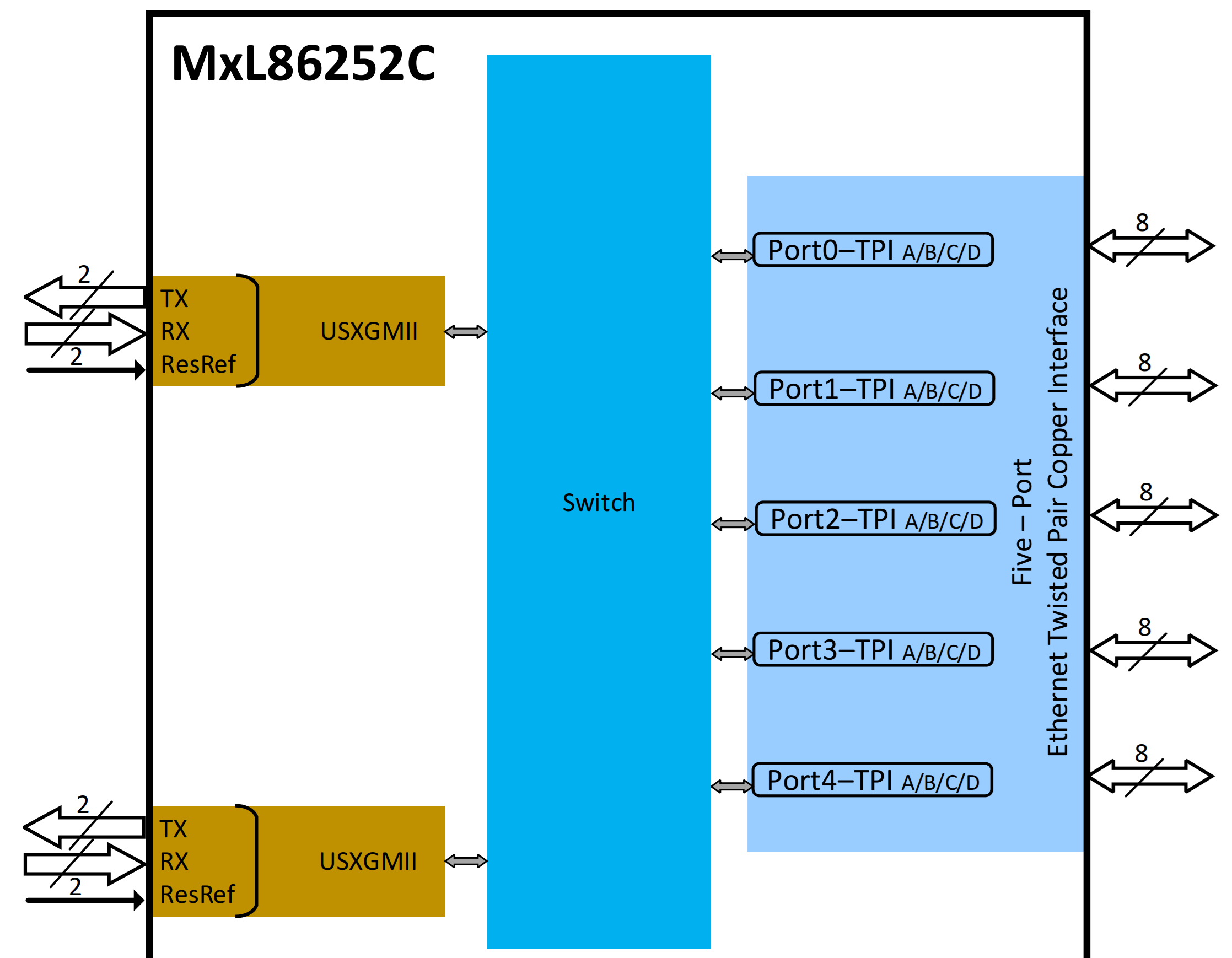
The four 2.5G RJ45 ports of BPI-R4Pro are expanded through MxL86252C(Port0~Port3).
|
The power consumption of MxL86252C also very high,a good heat dissipation effect heat sink must be used. |
¶ 2.5G iperf3 test
-
BPI-R4Lite← (2.5G LAN) BPI-R4Pro (10G WAN) →PC2
Details
root@R4Lite-A:/# iperf3 -c 10.0.1.12 -t 30 -i 30
Connecting to host 10.0.1.12, port 5201
[  5] local 10.0.11.126 port 33872 connected to 10.0.1.12 port 5201
[ ID] Interval           Transfer     Bitrate         Retr  Cwnd
[  5]   0.00-30.00  sec  8.22 GBytes  2.35 Gbits/sec   33   1.39 MBytes
- - - - - - - - - - - - - - - - - - - - - - - - -
[ ID] Interval           Transfer     Bitrate         Retr
[  5]   0.00-30.00  sec  8.22 GBytes  2.35 Gbits/sec   33             sender
[  5]   0.00-30.00  sec  8.21 GBytes  2.35 Gbits/sec                  receiver

iperf Done.
root@R4Lite-A:/#
root@R4Lite-A:/# iperf3 -c 10.0.1.12 -t 30 -i 30 -R
Connecting to host 10.0.1.12, port 5201
Reverse mode, remote host 10.0.1.12 is sending
[  5] local 10.0.11.126 port 42032 connected to 10.0.1.12 port 5201
[ ID] Interval           Transfer     Bitrate         Retr  Cwnd
[  5]   0.00-30.00  sec  8.22 GBytes  2.35 Gbits/sec
- - - - - - - - - - - - - - - - - - - - - - - - -
[ ID] Interval           Transfer     Bitrate         Retr
[  5]   0.00-30.00  sec  8.22 GBytes  2.35 Gbits/sec  1628             sender
[  5]   0.00-30.00  sec  8.22 GBytes  2.35 Gbits/sec                  receiver

iperf Done.
root@R4Lite-A:/#-
BPI-R4Lite-A← (2.5G LAN) BPI-R4Pro (2.5G LAN) →BPI-R4Lite-B
Details
root@R4Lite-A:/# iperf3 -c 10.0.11.217 -t 30 -i 30
Connecting to host 10.0.11.217, port 5201
[  5] local 10.0.11.126 port 59182 connected to 10.0.11.217 port 5201
[ ID] Interval           Transfer     Bitrate         Retr  Cwnd
[  5]   0.00-30.00  sec  8.22 GBytes  2.35 Gbits/sec    0   2.09 MBytes
- - - - - - - - - - - - - - - - - - - - - - - - -
[ ID] Interval           Transfer     Bitrate         Retr
[  5]   0.00-30.00  sec  8.22 GBytes  2.35 Gbits/sec    0             sender
[  5]   0.00-30.00  sec  8.22 GBytes  2.35 Gbits/sec                  receiver

iperf Done.
root@R4Lite-A:/# iperf3 -c 10.0.11.217 -t 30 -i 30 -R
Connecting to host 10.0.11.217, port 5201
Reverse mode, remote host 10.0.11.217 is sending
[  5] local 10.0.11.126 port 59276 connected to 10.0.11.217 port 5201
[ ID] Interval           Transfer     Bitrate         Retr  Cwnd
[  5]   0.00-30.00  sec  8.21 GBytes  2.35 Gbits/sec
- - - - - - - - - - - - - - - - - - - - - - - - -
[ ID] Interval           Transfer     Bitrate         Retr
[  5]   0.00-30.00  sec  8.21 GBytes  2.35 Gbits/sec    0             sender
[  5]   0.00-30.00  sec  8.21 GBytes  2.35 Gbits/sec                  receiver

iperf Done.
root@R4Lite-A:/#-
BPI-R4Lite← →(2.5G LAN) BPI-R4Pro
Details
root@R4Lite-A:/# iperf3 -c 10.0.11.1 -t 30 -i 30
Connecting to host 10.0.11.1, port 5201
[  5] local 10.0.11.126 port 38422 connected to 10.0.11.1 port 5201
[ ID] Interval           Transfer     Bitrate         Retr  Cwnd
[  5]   0.00-30.00  sec  8.22 GBytes  2.35 Gbits/sec    0    983 KBytes
- - - - - - - - - - - - - - - - - - - - - - - - -
[ ID] Interval           Transfer     Bitrate         Retr
[  5]   0.00-30.00  sec  8.22 GBytes  2.35 Gbits/sec    0             sender
[  5]   0.00-30.00  sec  8.22 GBytes  2.35 Gbits/sec                  receiver

iperf Done.
root@R4Lite-A:/# iperf3 -c 10.0.11.1 -t 30 -i 30 -R
Connecting to host 10.0.11.1, port 5201
Reverse mode, remote host 10.0.11.1 is sending
[  5] local 10.0.11.126 port 46554 connected to 10.0.11.1 port 5201
[ ID] Interval           Transfer     Bitrate         Retr  Cwnd
[  5]   0.00-30.00  sec  8.21 GBytes  2.35 Gbits/sec
- - - - - - - - - - - - - - - - - - - - - - - - -
[ ID] Interval           Transfer     Bitrate         Retr
[  5]   0.00-30.00  sec  8.21 GBytes  2.35 Gbits/sec    0             sender
[  5]   0.00-30.00  sec  8.21 GBytes  2.35 Gbits/sec                  receiver

iperf Done.
root@R4Lite-A:/#¶ MxL86252C update
| The current firmware version of the Mlx862 chip is V1.0.70.70. |
-
First, upload the Mlx files that need updating to the board.You can copy it via TFTP or USB drive.
-
Use the command ethswbox to check the status.
root@OpenWrt:~# ethswbox Ethernet SW Toolbox version 1.1.0.0 ... Updating symbolic links! -
Use the command fapi-GSW-FW-Update to load updates.
root@OpenWrt:~# fapi-GSW-FW-Update cmd: fapi-GSW-FW-Update 0: fapi_GSW_FW_Update done -
Burning using MDIO
root@OpenWrt:~# ssb_smdio_download “mxl fw name” cmd: ssb_smdio_download 1: xxx.bin FW size: 1466388 bytes Target is ready for downloading. Received START ACK from target, starting... image type: f48af48a, size 1: 166000, checksum 1: d19393ae, size 2: 0, checksum 2: 0 Received ACK of image header from target Erase flash Program flash ............................................ successfully download firmware to target FW Upload Failed - Register Read Failed -
Seeing the log above means the flashing process was successful. Next, reboot to apply the changes.
¶ 1G RJ45
The 1G RJ45 of BPI-R4Pro is connected to Port0 of the internal switch of MT7988A.
¶ 1G iperf3 test
-
BPI-R4Lite ←(1G LAN) BPI-R4Pro (10G WAN)→PC2
Details
root@R4Lite-D:/# iperf3 -c 10.0.1.12 -t 30 -i 30
Connecting to host 10.0.1.12, port 5201
[ 5] local 10.0.11.140 port 42284 connected to 10.0.1.12 port 5201
[ ID] Interval Transfer Bitrate Retr Cwnd
[ 5] 0.00-30.00 sec 3.29 GBytes 941 Mbits/sec 6 557 KBytes
- - - - - - - - - - - - - - - - - - - - - - - - -
[ ID] Interval Transfer Bitrate Retr
[ 5] 0.00-30.00 sec 3.29 GBytes 941 Mbits/sec 6 sender
[ 5] 0.00-30.00 sec 3.28 GBytes 940 Mbits/sec receiver
iperf Done.
root@R4Lite-D:/# iperf3 -c 10.0.1.12 -t 30 -i 30 -R
Connecting to host 10.0.1.12, port 5201
Reverse mode, remote host 10.0.1.12 is sending
[ 5] local 10.0.11.140 port 56924 connected to 10.0.1.12 port 5201
[ ID] Interval Transfer Bitrate Retr Cwnd
[ 5] 0.00-30.00 sec 3.28 GBytes 939 Mbits/sec
- - - - - - - - - - - - - - - - - - - - - - - - -
[ ID] Interval Transfer Bitrate Retr
[ 5] 0.00-30.00 sec 3.28 GBytes 940 Mbits/sec 37 sender
[ 5] 0.00-30.00 sec 3.28 GBytes 939 Mbits/sec receiver
iperf Done.
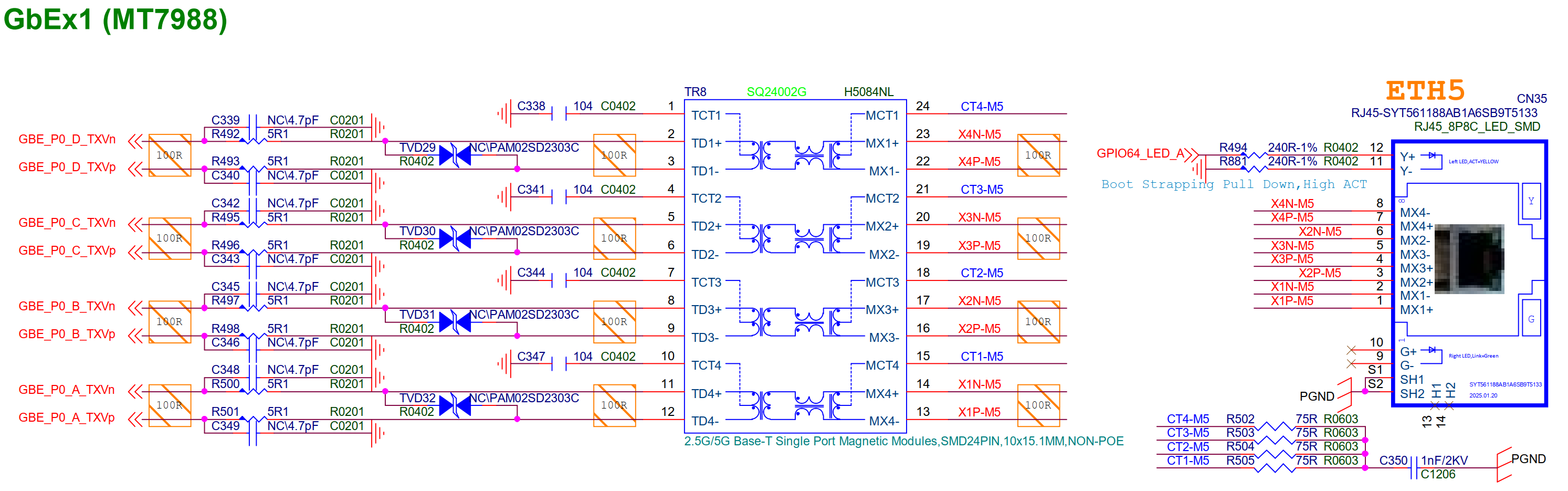
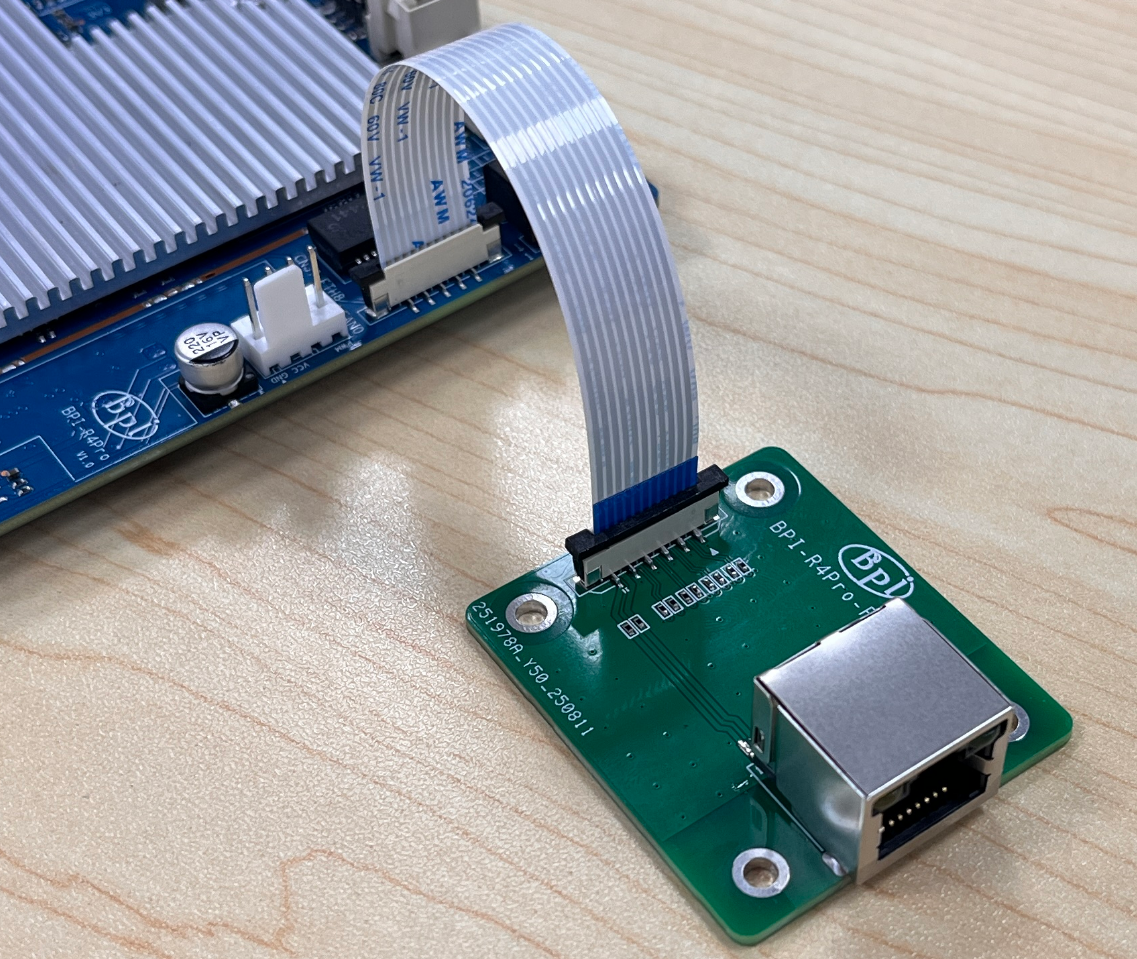
root@R4Lite-D:/#¶ 1G ETH FPC Connector
The 1G ETH FPC connector of BPI-R4Pro is connected to Port3 of the internal switch of MT7988A.
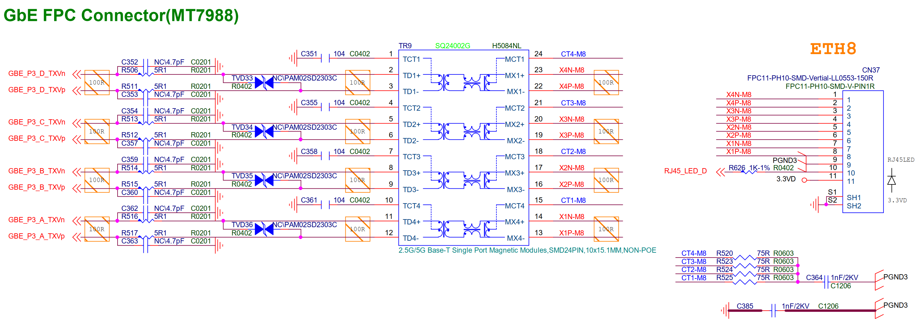
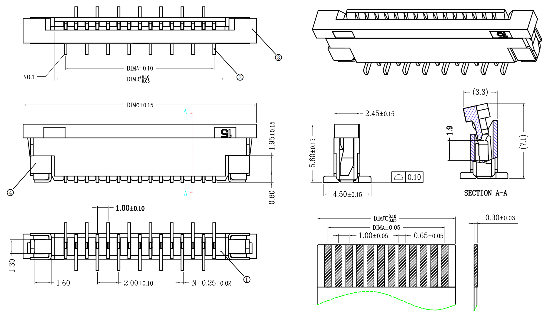
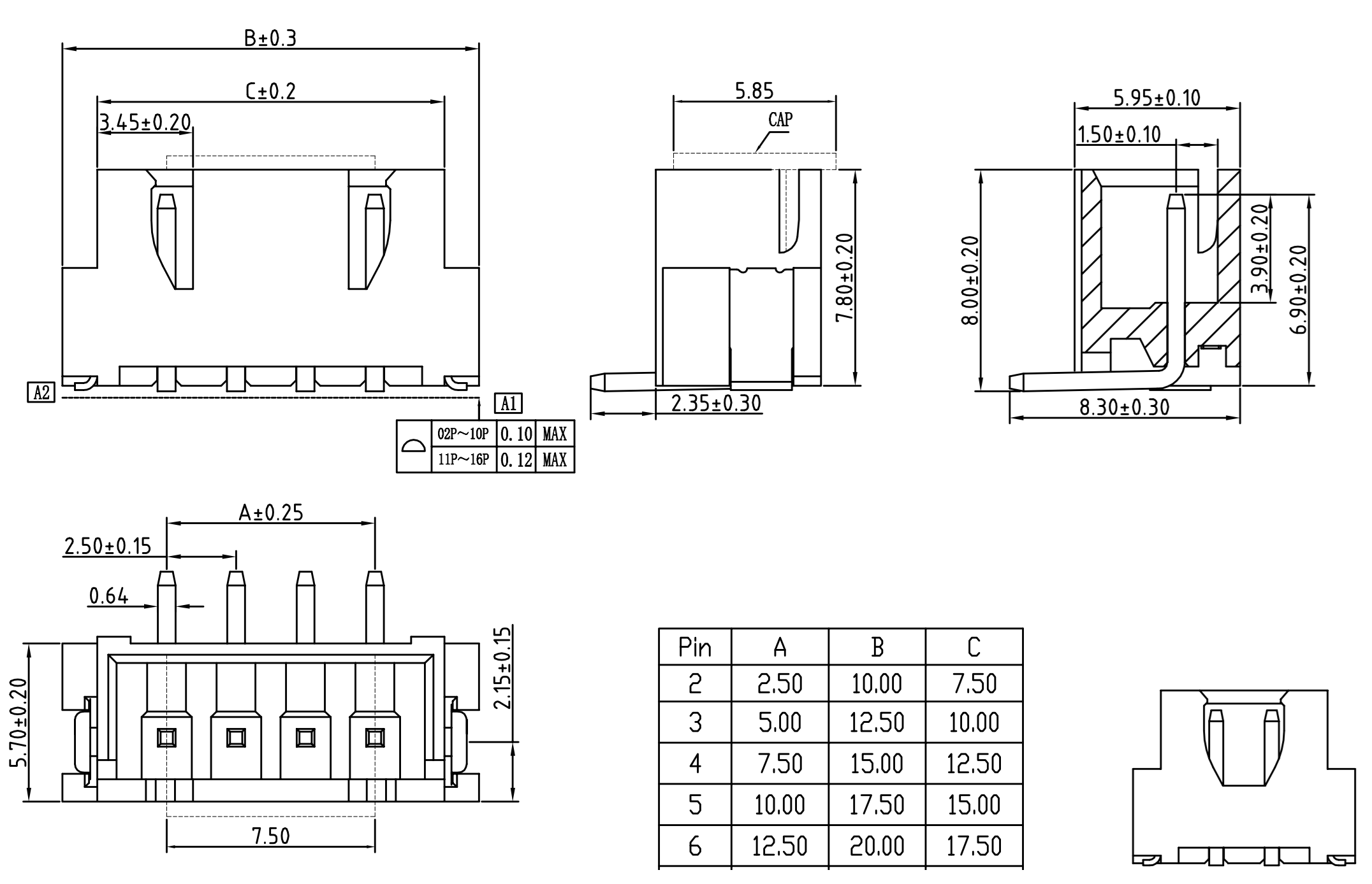
If you want to use this RJ45, you need a customized RJ45 adapter board and connect it with a 1.0MM Pitch 11PIN FPC (Flexible Printed Circuit).
The RJ45 adapter board layout needs to comply with its requirements, such as the differential Ethernet signals should be routed as 100Ω differential pairs, with suitable clearances, etc.
¶ 1G iperf3 test
-
BPI-R4Lite ←(1G FPC LAN) BPI-R4Pro (10G WAN)→PC2
Details
root@R4Lite-C:/# iperf3 -c 10.0.1.12 -t 30 -i 30
Connecting to host 10.0.1.12, port 5201
[  5] local 10.0.11.113 port 42596 connected to 10.0.1.12 port 5201
[ ID] Interval           Transfer     Bitrate         Retr  Cwnd
[  5]   0.00-30.00  sec  3.29 GBytes   941 Mbits/sec    9    581 KBytes
- - - - - - - - - - - - - - - - - - - - - - - - -
[ ID] Interval           Transfer     Bitrate         Retr
[  5]   0.00-30.00  sec  3.29 GBytes   941 Mbits/sec    9             sender
[  5]   0.00-30.00  sec  3.28 GBytes   940 Mbits/sec                  receiver

iperf Done.
root@R4Lite-C:/#
root@R4Lite-C:/# iperf3 -c 10.0.1.12 -t 30 -i 30 -R
Connecting to host 10.0.1.12, port 5201
Reverse mode, remote host 10.0.1.12 is sending
[  5] local 10.0.11.113 port 47484 connected to 10.0.1.12 port 5201
[ ID] Interval           Transfer     Bitrate         Retr  Cwnd
[  5]   0.00-30.00  sec  3.28 GBytes   939 Mbits/sec
- - - - - - - - - - - - - - - - - - - - - - - - -
[ ID] Interval           Transfer     Bitrate         Retr
[  5]   0.00-30.00  sec  3.28 GBytes   940 Mbits/sec   43             sender
[  5]   0.00-30.00  sec  3.28 GBytes   939 Mbits/sec                  receiver

iperf Done.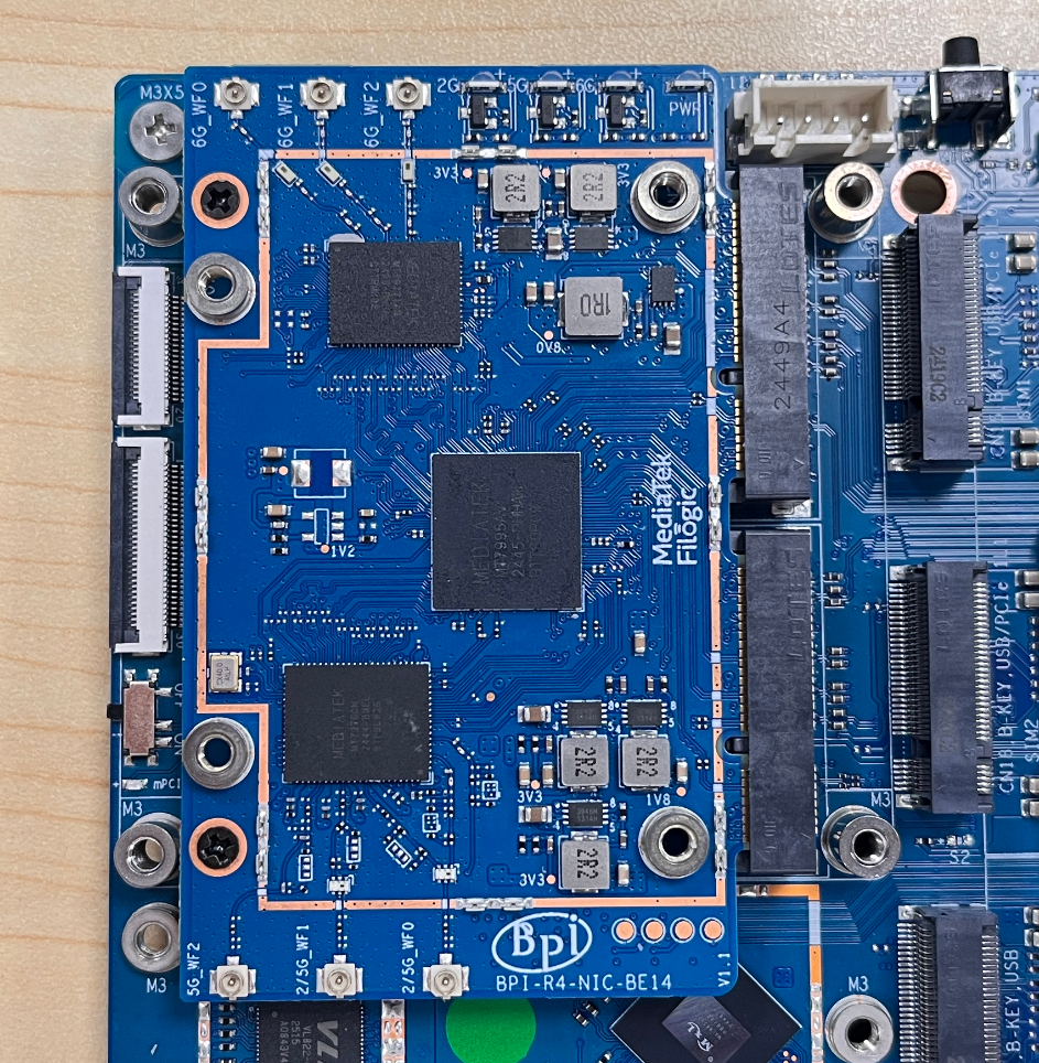
root@R4Lite-C:/#¶ miniPCIe Slot(For WiFi NIC)
You can insert the BPI WiFi NIC into CN7 and CN9 on top of BPI-R4Pro, and then fix it with two M2 screws.
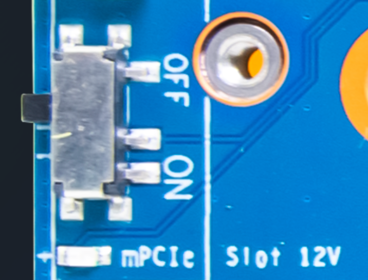
¶ 12V Power ON/OFF
BPI WiFi NIC module requires 12V power supply, so the power supply on the BPI-R4Pro must be turned on before powering on.
(SW4 is turned to the "ON" position, and the 12V LED will lights up when power on)
|
The 12V power supply will be supplied to the BPI WiFi NIC through PIN6/28/48 of the miniPCI socket. When plugging in other modules, be sure to turn off SW4 if you cannot confirm whether the module can withstand 12V. |
¶ 3.3V Power adjustment
Three GPIOs extended from PCA9555 can be used to turn off and the voltage of PCIe 3.3V adjustment.
Normally you do not need to adjust this voltage.
Details
| miniPCIe Slot 3.3V Power | ||
|---|---|---|
GPIO |
Output=High |
Output=Low |
PCA_A_IO1_0/mPCIe_A_PDN |
PCIeA_3P3V = ON |
PCIeA_3P3V = OFF |
PCA_A_IO1_1/mPCIe_B_PDN |
PCIeB_3P3V = ON |
PCIeB_3P3V = OFF |
PCA_A_IO0_7/mPCIe_AB_Vset |
PCIeA_3P3V=PCIeB_3P3V=3.57V |
PCIeA_3P3V=PCIeB_3P3V=3.3V |
¶ PCIe
The BPI WiFi NIC BE14/BE19 requires two 2lane PCIe , but the standard for miniPCIe slots only defines one 1lane PCIe.
Therefore, we used two miniPCIe slots and modified the pins 17/19/45/47 of each slot to be the second lane signal of PCIe.
Except these four PINs, the others are standard definitions, so you can also use other modules.
¶ USB2.0
The two miniPCIe sockets each reserve a pair of USB2.0 signals extended from the USB2.0 HUB for expansion of other modules.
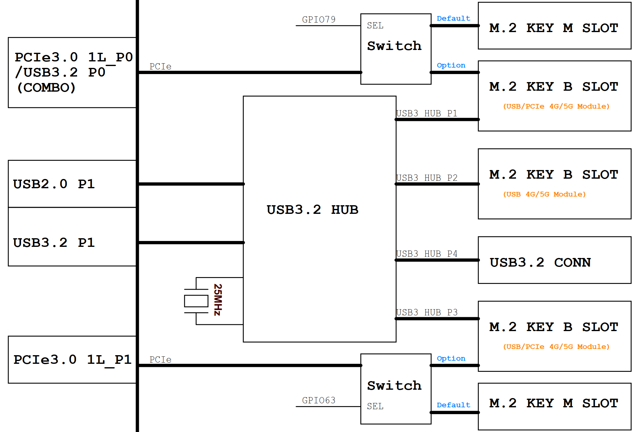
¶ M.2 B-KEY Slot(For 4G/5G Cellular Module)
The BPI-R4Pro has three M.2 B-KEY slots, all for 4G/5G Cellular Modules.
Each slot supports a pair of USB2.0 and USB3.0 signals, both extended via a USB 3.0 hub.
In addition, the CN15 and CN18 slots each have an additional PCIe3.0 1lane signal.
¶ Power
All modules are powered by independent step-down DC-DC.
GPIO can be used to shut down the power output and adjust the output voltage.
¶ Power ON/OFF
The power on/off control is as follows.
Details
| M.2 B-KEY Slot Power | ||
|---|---|---|
GPIO |
Output=High |
Output=Low |
PCA_A_IO0_0/BKEY-A-PDN |
VDD_BKEY_A = ON |
VDD_BKEY_A = OFF |
PCA_A_IO0_2/BKEY-B-PDN |
VDD_BKEY_B = ON |
VDD_BKEY_B = OFF |
PCA_A_IO0_4/BKEY-C-PDN |
VDD_BKEY_C = ON |
VDD_BKEY_C = OFF |
¶ 3.3V Power adjustment
The operating voltage of most 5G modules is 3.3V~4.2V. Due to the large current, using 3.3V will cause module instability,
so it is recommended to adjust it to 3.95V.
But before adjustment, please make sure that your 5G module can withstand 3.95V!!!
Details
| M.2 B-KEY Slot 3.3V Power adjustment | ||
|---|---|---|
GPIO |
Output=High |
Output=Low |
PCA_A_IO0_1/BKEY-A-Vset |
VDD_BKEY_A = 3.95V |
VDD_BKEY_A = 3.3V |
PCA_A_IO0_3/BKEY-B-Vset |
VDD_BKEY_B = 3.95V |
VDD_BKEY_B = 3.3V |
PCA_A_IO0_5/BKEY-C-Vset |
VDD_BKEY_C = 3.95V |
VDD_BKEY_C = 3.3V |
¶ Reset
Each module can be reset by GPIO.
Details
| M.2 B-KEY Slot Reset | ||
|---|---|---|
GPIO |
Output=High |
Output=Low |
PCA_A_IO1_3/BKEY-A-RST |
Module = Reset |
Module = Functional |
PCA_A_IO1_4/BKEY-B-RST |
Module = Reset |
Module = Functional |
PCA_A_IO1_5/BKEY-C-RST |
Module = Reset |
Module = Functional |
¶ SIM Card
Each M.2 B-KEY Slot supports two sets of SIM card signals.
We connected SIMA to the onboard NANO SIM Slot and SIMB to the eSIM.
However, the eSIM does not have components onboard. If you need it, please contact our sales.
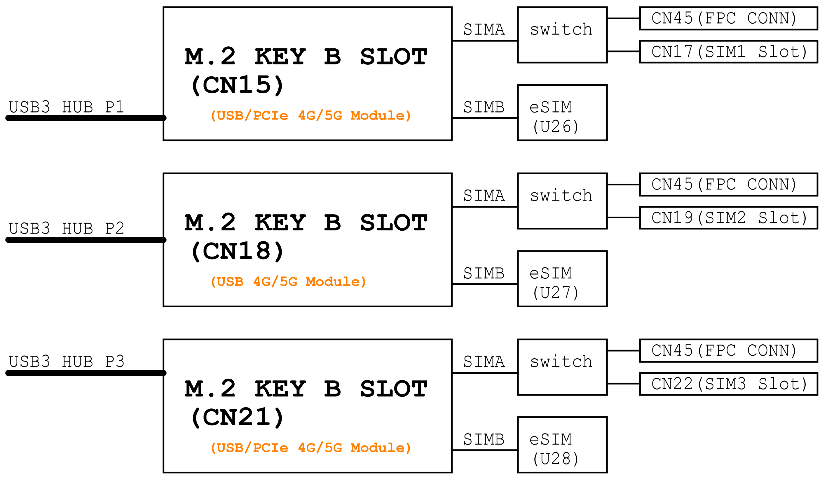
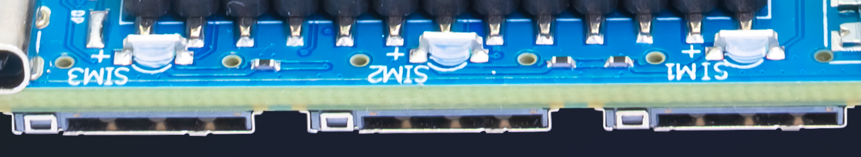
¶ Onboard NANO SIM Slot
SIM1 can use the onboard NANO SIM Slot or an external SIM Slot (this requires a self-designed expansion board connected via CN45)
when "PCA_A_IO0_6/SIM_SEL" Output=Low,SIM1 Connect to Onboard NANO SIM Slot,
when "PCA_A_IO0_6/SIM_SEL" Output=High,SIM1 Route to FPC Connector,
¶ External SIM Slot Conector
The SIM card signals from the three B-KEYs and two miniPCIe sockets can be connected to the FPC Connector (CN45).
note:: This allows you to easily design a SIM card adapter board to fit your enclosure.
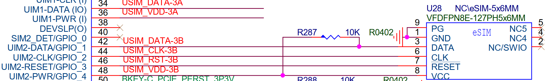
¶ eSIM
PIN42/44/46/48 of M.2 B-KEY Slot is the second set of SIM card signals.
NOTE : This requires your module to support it.
¶ Cellular network LED
PIN10 of each M.2 B-KEY Slot is connected to an LED. This LED is the module’s network status indicator output.
For specific functions, please refer to your module’s datasheet.

¶ External LED Conector
We also route the LED signal to FPC slot(CN40).
If necessary, you can design an LED adapter board to adapt to your enclosure.
¶ USB3.0
Most 4G/5G modules can use USB2.0/USB3.0 for communication.
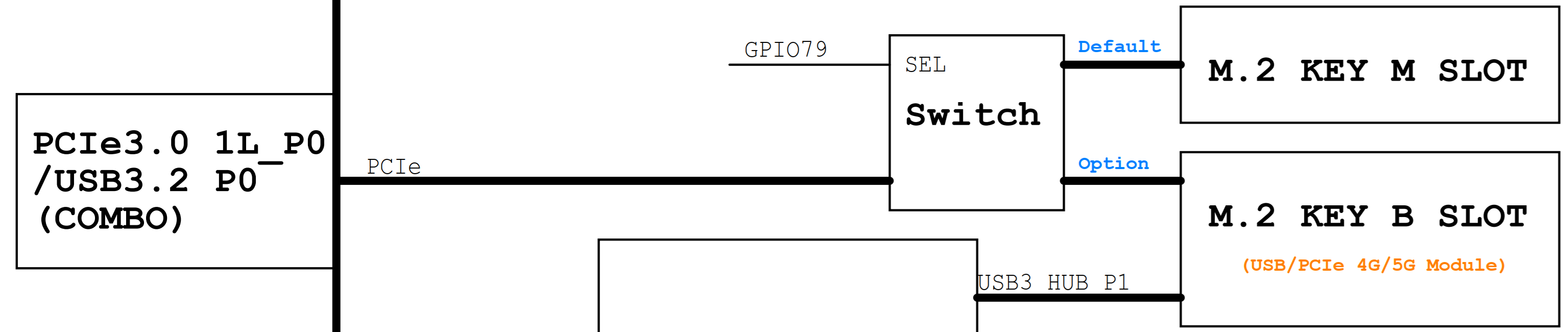
¶ PCIe
MT7988A has only four PCIe, two of which are used for WiFi connections,
and the other two PCIe3.0 1L0 and PCIe3.0 1L1 can be routed to M.2 M-KEY or M.2 B-KEY.
Details
| M.2 B-KEY Slot PCIe | ||
|---|---|---|
GPIO |
Output=High |
Output=Low |
GPIO79/PCIE_1L0_SEL_1p8V |
PCIE_1L_0 = M.2 M-KEY(CN13) |
PCIE_1L_0 = M.2 B-KEY(CN15) |
GPIO63/PCIE_1L1_SEL_1p8V |
PCIE_1L_1 = M.2 M-KEY(CN14) |
PCIE_1L_1 = M.2 B-KEY(CN18) |
¶ M.2 M-KEY Slot(For PCIe NVME SSD)
The size of the M.2 M-KEY Slot is 2280, which can be connected to PCIe NVME SSD or PCIe to SATA, PCIe to Ethernet and other modules.
However, because the PCIe signal is multiplexed with the M.2 B-KEY Slot,
if you want to use it in the M.2 M-KEY Slot, you need to set GPIO79 or GPIO63 output high,
so that the corresponding signal can be switched over.
Details
| M.2 M-KEY Slot PCIe | ||
|---|---|---|
GPIO |
Output=High |
Output=Low |
GPIO79/PCIE_1L0_SEL_1p8V |
PCIE_1L_0 = M.2 M-KEY(CN13) |
PCIE_1L_0 = M.2 B-KEY(CN15) |
GPIO63/PCIE_1L1_SEL_1p8V |
PCIE_1L_1 = M.2 M-KEY(CN14) |
PCIE_1L_1 = M.2 B-KEY(CN18) |
¶ USB connector
¶ USB3.2 connector
BPI-R4Pro has a USB3.2 Type-A connector that can be used to connect a USB flash drive or other USB devices.
The power output of the USB3.2 connector (CN11) is 5V/1300mA, which can be turned off via "PCA_A_IO1_3/VBUS_AB_PDN" output low.
¶ USB2.0 connector
BPI-R4Pro has a USB2.0 Type-A connector that can be used to connect a USB flash drive or other USB devices.
The power output of the USB2.0 connector (CN12) is 5V/1300mA, which can be turned off via "PCA_A_IO1_3/VBUS_AB_PDN" output low.
¶ USB TypC Debug Console connector
The BPI-R4Pro has an onboard USB-to-UART chip(HT42B534-2), connected to the MT7988A’s Debug UART.
When connected USB Type-c connector(CN41) to PC, a USB-to-serial device will appear, which can be used for debugging.
Terminal setting : Baud=115200,Data bits: 8bit,Parity: none,Stop: 1bit, Flow control: none,

¶ MicroSD Card
The BPI-R4Pro has a Micro SD (Secure Digital) card slot, which can be used for bootup and storage.
However, the MT7988A only has one controller of MSDC, which outputs two pinmux ports for SD 4.5 and eMMC 5.1,
so you can only choose between SD and eMMC functions.
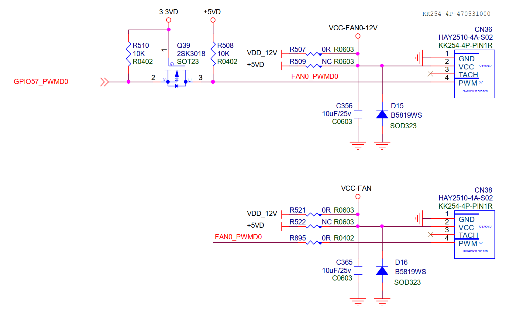
¶ FAN
The BPI-R4Pro has two fan connectors, with pin assignments compatible with 4-wire PWM-controlled fans on Intel PC motherboards.
It operates with a 12V supply voltage and supports PWM speed control, but lacks a sense pin for speed detection.
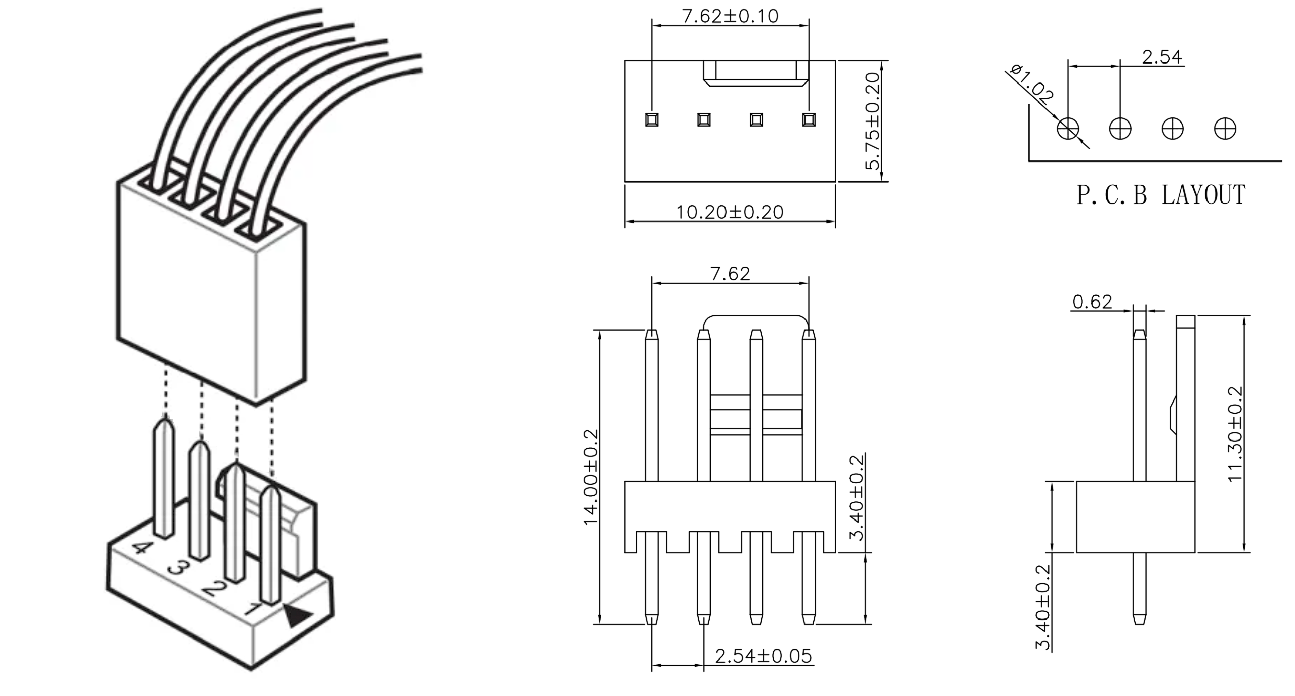
These two FAN connectors are controlled by the same PWM (GPIO57_PWMD0).
¶ RTC
Built-in one RTC clock chip, and you only need to install a 3V CR1220 battery to work.
¶ EEPROM
Built-in one EEPROM chip (P24C02A), can be used to store small amounts of data.
¶ Buttons
¶ Reset
| In the BPI-R4Pro-8X-BE14-MT76-OpenWRT24.10-DSA-251229 image, a short press of RST restarts the system, while a long press resets the system. |
A reset button is connect to GPIO13,used for restore to factory default settings.
¶ WPS
A reset button is connect to GPIO14,used for new devices quickly connect to the router.
¶ LEDs
BPI-R4Pro has LEDs to indicate various operating states, including power, WiFi, Ethernet, 4G/5G cellular, SSD, etc.
-
1x Power Green LED, Silkscreen "PWR" on the PCB,lights up when powered on and cannot be controlled by the software.
-
1x Status Red LED,Silkscreen "R" on the PCB,Controlled by GPIO "PCA_A_IO1_7/SYS_LEDR".
-
1x Status Blue LED,Silkscreen "B" on the PCB,Controlled by GPIO "PCA_A_IO1_6/SYS_LEDB".
-
3x WiFi Status Blue LEDs,The silk screen printing"W2G","W5G","W6G".
The specific function depends on the module. Some modules do not have this function (including BPI-BE14 V1.0). -
2x SSD Status Blue LEDs,The silk screen printing"SSD1","SSD2", Controlled by SSD.
-
3x 5G cellular Status Blue LEDs,The silk screen printing"SIM1","SIM2","SIM3",Controlled by 5G Module.
-
Each 10G/2.5G RJ45 has two LEDs, and each 1G RJ45 has one LED to indicate the network status.
¶ DC-IN
BPI-R4Pro requires a single +12V supply,and has multiple power supply , including DC power adapter, USB PD, POE, etc.
The supply voltage range is 9~24V, 12V or 20V is recommended, and it will automatically shut down when it exceeds 25.3V.
¶ DCIN(5521)
You can use a 12V/5A power adapter and plug it into the CN44 to power it.
However, if other power supply exist at the same time, it will be switched to other power supply.
The dimensions of the CN44 slot are as follows(Inner Positive, Outer Negative):
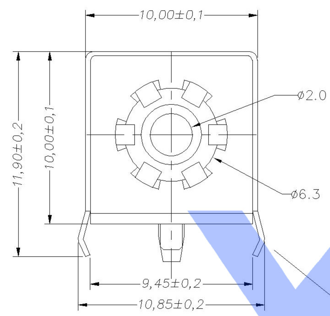
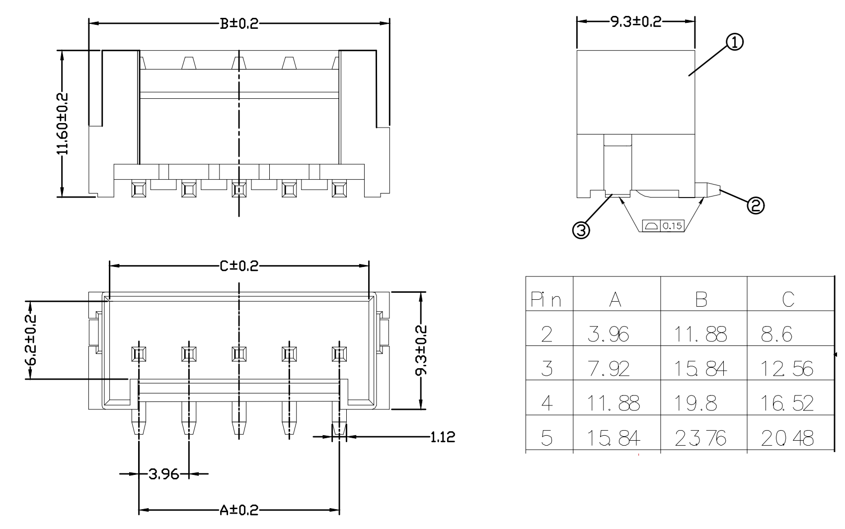
¶ DCIN(VH396)
You can also use a VH3.96 plug and connect it to CN6 for power supply.
The dimensions of the CN46 slot are as follows:
¶ USB TypeC PD
The USB Type-C PD connector is connected to a CH224K chip, which is used to communicate with the USB adapter and allow the adapter to output 20V voltage.
It is recommended to use a PD power supply that can output 20V and 65W or more.
¶ POE
You can use the BPI-RT5400-12V module, but this module does not exceed 30W at most. So when more peripherals are connected, the power consumption will exceed the maximum power of RT5400. Therefore, it is recommended to change to other power supply.
¶ DC-OUT
BPI-R4Pro has two power output sockets, but it is not recommended to use them to connect too many devices,
because it consumes too much power and may cause BPI-R4Pro to work unstably.
The dimensions of the CN2/CN3 slot are as follows:
¶ DCOUT(CN3,XH2.54-2PIN)
Connect directly to VDD_SYS_IN, the output voltage is equal to the input‘s.
¶ DCOUT(CN2,XH2.54-4PIN)
This slot provides two voltage outputs: +12V and +5V. The +5V is generated by the MT6682A PMIC. This voltage supplies power to many other devices, so it’s recommended not to connect high-power devices to avoid affecting system stability.
The 12V is generated by a separate DC-DC converter, capable of providing approximately 3A.
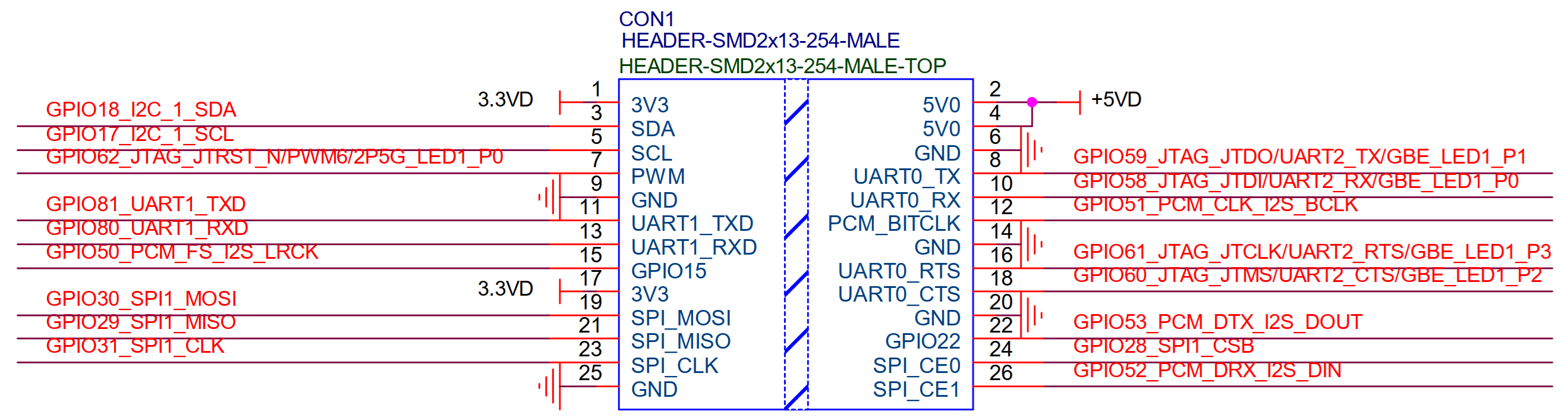
¶ 26PIN GPIO Header
The 26-pin GPIO Header contains 17 GPIOs. All GPIOs are 3.3V. Some GPIOs can be set to JTAG, I2C, UART, SPI and other functions.
¶ PIN Definition
¶ FAN (CN36/CN38)
Details
| BPI-R4Pro FAN Connector PIN define | |
|---|---|
PIN No. |
Connection Destination |
1 |
GND |
2 |
12V |
3 |
NC |
4 |
PWM(5V) |
¶ 26 GPIO Header(CON1)
Details
| BPI-R4Pro 26 GPIO Header(CON1) PIN define | |||
|---|---|---|---|
Connection Destination |
PIN No. |
PIN No. |
Connection Destination |
3.3VD |
1 |
2 |
5VD |
GPIO18/I2C_1_SDA |
3 |
4 |
5VD |
GPIO17/I2C_1_SCL |
5 |
6 |
GND |
GPIO62/JTAG_JTRST_N/PWM6 |
7 |
8 |
GPIO59/JTAG_JTDO/UART1_TX/UART2_TX |
GND |
9 |
10 |
GPIO58/JTAG_JTDI/UART1_RX/UART2_RX |
GPIO81/UART1_TXD |
11 |
12 |
GPIO51/PCM_CLK_I2S_BCLK |
GPIO80/UART1_RXD |
13 |
14 |
GND |
GPIO50/PCM_FS_I2S_LRCK |
15 |
16 |
GPIO61/JTAG_JTCLK/UART1_RTS/UART2_RTS |
3.3VD |
17 |
18 |
GPIO60/JTAG_JTMS/UART1_CTS/UART2_CTS |
GPIO30/SPI1_MOSI |
19 |
20 |
GND |
GPIO29/SPI1_MISO |
21 |
22 |
GPIO53/PCM_DTX_I2S_DOUT |
GPIO31/SPI1_CLK |
23 |
24 |
GPIO28/SPI1_CSB |
GND |
25 |
26 |
GPIO52/PCM_DRX_I2S_DIN |
¶ miniPCIe Slot1(CN7)
Details
| BPI-R4Pro miniPCIe Slot1(CN7) PIN define | |||
|---|---|---|---|
Connection Destination |
PIN No. |
PIN NO. |
Connection Destination |
PCIE_2L_0_WAKE_N(3.3V) |
1 |
2 |
PCIe_3V3#2 |
NI |
3 |
4 |
GND |
NI |
5 |
6 |
PCIe_12V#2 |
PCIE_2L_0_CLKREQ_N(3.3V) |
7 |
8 |
mPCIe_A_USIM_VDD |
GND |
9 |
10 |
mPCIe_A_USIM_DATA |
PCIE_2L_0_SOC_CKn |
11 |
12 |
mPCIe_A_USIM_CLK |
PCIE_2L_0_SOC_CKp |
13 |
14 |
mPCIe_A_USIM_RST |
GND |
15 |
16 |
NI |
PCIE_2L_0_LN1_SOC_RXn |
17 |
18 |
GND |
PCIE_2L_0_LN1_SOC_RXp |
19 |
20 |
NI |
GND |
21 |
22 |
PCIE_2L_0_PRESET_N(3.3V) |
PCIE_2L_0_LN0_SOC_RXn |
23 |
24 |
PCIe_3V3#2 |
PCIE_2L_0_LN0_SOC_RXp |
25 |
26 |
GND |
GND |
27 |
28 |
PCIe_12V#2 |
GND |
29 |
30 |
I2C_SCL_EXT_WiFi |
PCIE_2L_0_LN0_SOC_TXn |
31 |
32 |
I2C_SDA_EXT_WiFi |
PCIE_2L_0_LN0_SOC_TXp |
33 |
34 |
GND |
GND |
35 |
36 |
USB2HUB-D3M |
GND |
37 |
38 |
USB2HUB-D3P |
PCIe_3V3#2 |
39 |
40 |
GND |
PCIe_3V3#2 |
41 |
42 |
WiFi-LED-5G |
GND |
43 |
44 |
mPCIe_A_USIM_DET |
PCIE_2L_0_LN1_SOC_TXn |
45 |
46 |
WiFi-LED-2G |
PCIE_2L_0_LN1_SOC_TXp |
47 |
48 |
PCIe_12V#2 |
GND |
49 |
50 |
GND |
MT7996_EINT_RESETB(1.8V) |
51 |
52 |
PCIe_3V3#2 |
¶ miniPCIe Slot2(CN9)
Details
| BPI-R4Pro miniPCIe Slot2(CN9) PIN define | |||
|---|---|---|---|
Connection Destination |
PIN |
PIN |
Connection Destination |
PCIE_2L_1_WAKE_N(3.3V) |
1 |
2 |
PCIe_3V3#1 |
NI |
3 |
4 |
GND |
NI |
5 |
6 |
PCIe_12V#1 |
PCIE_2L_1_CLKREQ_N(3.3V) |
7 |
8 |
mPCIe_B_USIM_VDD |
GND |
9 |
10 |
mPCIe_B_USIM_DATA |
PCIE_2L_1_SOC_CKn |
11 |
12 |
mPCIe_B_USIM_CLK |
PCIE_2L_1_SOC_CKp |
13 |
14 |
mPCIe_B_USIM_RST |
GND |
15 |
16 |
NI |
PCIE_2L_1_LN1_SOC_RXn |
17 |
18 |
GND |
PCIE_2L_1_LN1_SOC_RXp |
19 |
20 |
NI |
GND |
21 |
22 |
PCIE_2L_1_PRESET_N(3.3V) |
PCIE_2L_1_LN0_SOC_RXn |
23 |
24 |
PCIe_3V3#1 |
PCIE_2L_1_LN0_SOC_RXp |
25 |
26 |
GND |
GND |
27 |
28 |
PCIe_12V#1 |
GND |
29 |
30 |
I2C_SCL_EXT_WiFi |
PCIE_2L_1_LN0_SOC_TXn |
31 |
32 |
I2C_SDA_EXT_WiFi |
PCIE_2L_1_LN0_SOC_TXp |
33 |
34 |
GND |
GND |
35 |
36 |
USB2HUB-D2M |
GND |
37 |
38 |
USB2HUB-D2P |
PCIe_3V3#1 |
39 |
40 |
GND |
PCIe_3V3#1 |
41 |
42 |
WiFi-LED-6G |
GND |
43 |
44 |
mPCIe_B_USIM_DET |
PCIE_2L_1_LN1_SOC_TXn |
45 |
46 |
NI |
PCIE_2L_1_LN1_SOC_TXp |
47 |
48 |
PCIe_12V#1 |
GND |
49 |
50 |
GND |
NI |
51 |
52 |
PCIe_3V3#1 |
¶ M.2 B-KEY Slot1(CN15)
Details
| BPI-R4Pro M.2 B-KEY Slot1(CN15) PIN define | |||
|---|---|---|---|
Connection Destination |
PIN No. |
PIN NO. |
Connection Destination |
NI |
1 |
2 |
VDD_BKEY_A |
GND |
3 |
4 |
VDD_BKEY_A |
GND |
5 |
6 |
NI(10K PullUp to 3.3V) |
USBHUB_USB1_Dp |
7 |
8 |
NI |
USBHUB_USB1_Dn |
9 |
10 |
BKEY-A-NET-STUn LED |
GND |
11 |
12 |
NOTCH |
NOTCH |
13 |
14 |
NOTCH |
NOTCH |
15 |
16 |
NOTCH |
NOTCH |
17 |
18 |
NOTCH |
NOTCH |
19 |
20 |
NI |
NI |
21 |
22 |
NI |
NI |
23 |
24 |
NI |
NI |
25 |
26 |
NI |
GND |
27 |
28 |
NI |
USBHUB_USB1_RXn |
29 |
30 |
USIM_RST-1A |
USBHUB_USB1_RXp |
31 |
32 |
USIM_CLK-1A |
GND |
33 |
34 |
USIM_DATA-1A |
USBHUB_USB1_TXn |
35 |
36 |
USIM_VDD-1A |
USBHUB_USB1_TXp |
37 |
38 |
NI |
GND |
39 |
40 |
NI |
PCIE_SW_A_C_RXn |
41 |
42 |
USIM_DATA-1B |
PCIE_SW_A_C_RXp |
43 |
44 |
USIM_CLK-1B |
GND |
45 |
46 |
USIM_RST-1B |
PCIE_SW_A_C_TXn |
47 |
48 |
USIM_VDD-1B |
PCIE_SW_A_C_TXp |
49 |
50 |
BKEY-A-PRESET_3P3V |
GND |
51 |
52 |
BKEY-A-CLKREQ_3P3V |
PCIE_SW_A_C_CKn |
53 |
54 |
BKEY-A-WAKE_3P3V |
PCIE_SW_A_C_CKp |
55 |
56 |
NI |
GND |
57 |
58 |
NI |
NI |
59 |
60 |
NI |
NI |
61 |
62 |
NI |
NI |
63 |
64 |
NI |
NI |
65 |
66 |
USIM_DET-1A |
BKEY-A-RST |
67 |
68 |
NI |
NI |
69 |
70 |
VDD_BKEY_A |
GND |
71 |
72 |
VDD_BKEY_A |
GND |
73 |
74 |
VDD_BKEY_A |
NI |
75 |
||
¶ M.2 B-KEY Slot2(CN18)
Details
| BPI-R4Pro M.2 B-KEY Slot2(CN18) PIN define | |||
|---|---|---|---|
Connection Destination |
PIN No. |
PIN NO. |
Connection Destination |
NI |
1 |
2 |
VDD_BKEY_B |
GND |
3 |
4 |
VDD_BKEY_B |
GND |
5 |
6 |
NI(10K PullUp to 3.3V) |
USBHUB_USB2_Dp |
7 |
8 |
NI |
USBHUB_USB2_Dn |
9 |
10 |
BKEY-B-NET-STUn LED |
GND |
11 |
12 |
NOTCH |
NOTCH |
13 |
14 |
NOTCH |
NOTCH |
15 |
16 |
NOTCH |
NOTCH |
17 |
18 |
NOTCH |
NOTCH |
19 |
20 |
NI |
NI |
21 |
22 |
NI |
NI |
23 |
24 |
NI |
NI |
25 |
26 |
NI |
GND |
27 |
28 |
NI |
USBHUB_USB2_RXn |
29 |
30 |
USIM_RST-2A |
USBHUB_USB2_RXp |
31 |
32 |
USIM_CLK-2A |
GND |
33 |
34 |
USIM_DATA-2A |
USBHUB_USB2_TXn |
35 |
36 |
USIM_VDD-2A |
USBHUB_USB2_TXp |
37 |
38 |
NI |
GND |
39 |
40 |
NI |
PCIE_SW_B_C_RXn |
41 |
42 |
USIM_DATA-2B |
PCIE_SW_B_C_RXp |
43 |
44 |
USIM_CLK-2B |
GND |
45 |
46 |
USIM_RST-2B |
PCIE_SW_B_C_TXn |
47 |
48 |
USIM_VDD-2B |
PCIE_SW_B_C_TXp |
49 |
50 |
BKEY-B-PRESET_3P3V |
GND |
51 |
52 |
BKEY-B-CLKREQ_3P3V |
PCIE_SW_B_C_CKn |
53 |
54 |
BKEY-B-WAKE_3P3V |
PCIE_SW_B_C_CKp |
55 |
56 |
NI |
GND |
57 |
58 |
NI |
NI |
59 |
60 |
NI |
NI |
61 |
62 |
NI |
NI |
63 |
64 |
NI |
NI |
65 |
66 |
USIM_DET-2A |
BKEY-A_RSTn |
67 |
68 |
NI |
NI |
69 |
70 |
VDD_BKEY_B |
GND |
71 |
72 |
VDD_BKEY_B |
GND |
73 |
74 |
VDD_BKEY_B |
NI |
75 |
||
¶ M.2 B-KEY Slot3(CN21)
Details
| BPI-R4Pro M.2 B-KEY Slot3(CN21) PIN define | |||
|---|---|---|---|
Connection Destination |
PIN No. |
PIN NO. |
Connection Destination |
NI |
1 |
2 |
VDD_BKEY_C |
GND |
3 |
4 |
VDD_BKEY_C |
GND |
5 |
6 |
NI(10K PullUp to 3.3V) |
USBHUB_USB4_Dp |
7 |
8 |
NI |
USBHUB_USB4_Dn |
9 |
10 |
BKEY-C-NET-STUn LED |
GND |
11 |
12 |
NOTCH |
NOTCH |
13 |
14 |
NOTCH |
NOTCH |
15 |
16 |
NOTCH |
NOTCH |
17 |
18 |
NOTCH |
NOTCH |
19 |
20 |
NI |
NI |
21 |
22 |
NI |
NI |
23 |
24 |
NI |
NI |
25 |
26 |
NI |
GND |
27 |
28 |
NI |
USBHUB_USB4_RXn |
29 |
30 |
USIM_RST-3A |
USBHUB_USB4_RXp |
31 |
32 |
USIM_CLK-3A |
GND |
33 |
34 |
USIM_DATA-3A |
USBHUB_USB4_TXn |
35 |
36 |
USIM_VDD-3A |
USBHUB_USB4_TXp |
37 |
38 |
NI |
GND |
39 |
40 |
NI |
NI |
41 |
42 |
USIM_DATA-3B |
NI |
43 |
44 |
USIM_CLK-3B |
GND |
45 |
46 |
USIM_RST-3B |
NI |
47 |
48 |
USIM_VDD-3B |
NI |
49 |
50 |
BKEY-C_PCIE_PERST_3P3V |
GND |
51 |
52 |
BKEY-C_PCIE_CLKREQ_3P3V |
NI |
53 |
54 |
BKEY-C_PCIE_PEWAKE_3P3V |
NI |
55 |
56 |
NI |
GND |
57 |
58 |
NI |
NI |
59 |
60 |
NI |
NI |
61 |
62 |
NI |
NI |
63 |
64 |
NI |
NI |
65 |
66 |
USIM_DET-3A |
BKEY-C_RSTn |
67 |
68 |
NI |
NI |
69 |
70 |
VDD_BKEY_C |
GND |
71 |
72 |
VDD_BKEY_C |
GND |
73 |
74 |
VDD_BKEY_C |
NI |
75 |
||
¶ M.2 M-KEY Slot1(CN13)
Details
| BPI-R4Pro M.2 M-KEY Slot1(CN13) PIN define | |||
|---|---|---|---|
Connection Destination |
PIN |
PIN |
Connection Destination |
GND |
1 |
2 |
VDD_MKEY_A |
GND |
3 |
4 |
VDD_MKEY_A |
NI |
5 |
6 |
NI |
NI |
7 |
8 |
NI |
GND |
9 |
10 |
MKEY-A-SSD-LEDn |
NI |
11 |
12 |
VDD_MKEY_A |
NI |
13 |
14 |
VDD_MKEY_A |
GND |
15 |
16 |
VDD_MKEY_A |
NI |
17 |
18 |
VDD_MKEY_A |
NI |
19 |
20 |
NI |
GND |
21 |
22 |
NI |
NI |
23 |
24 |
NI |
NI |
25 |
26 |
NI |
GND |
27 |
28 |
NI |
NI |
29 |
30 |
NI |
NI |
31 |
32 |
NI |
GND |
33 |
34 |
NI |
NI |
35 |
36 |
NI |
NI |
37 |
38 |
NI |
GND |
39 |
40 |
NI |
PCIE_SW_A_B_RXn |
41 |
42 |
NI |
PCIE_SW_A_B_RXp |
43 |
44 |
NI |
GND |
45 |
46 |
NI |
PCIE_SW_A_B_TXn |
47 |
48 |
NI |
PCIE_SW_A_B_TXp |
49 |
50 |
MKEY-A-PRESET_3P3V |
GND |
51 |
52 |
MKEY-A-CLKREQ_3P3V |
PCIE_SW_A_B_CKn |
53 |
54 |
MKEY-A-WAKE_3P3V |
PCIE_SW_A_B_CKp |
55 |
56 |
NI |
GND |
57 |
58 |
NI |
NOCTH |
59 |
60 |
NOCTH |
NOCTH |
61 |
62 |
NOCTH |
NOCTH |
63 |
64 |
NOCTH |
NOCTH |
65 |
66 |
NOCTH |
NI |
67 |
68 |
NI |
NI |
69 |
70 |
VDD_MKEY_A |
GND |
71 |
72 |
VDD_MKEY_A |
GND |
73 |
74 |
VDD_MKEY_A |
GND |
75 |
||
¶ M.2 M-KEY Slot2(CN14)
Details
| BPI-R4Pro M.2 M-KEY Slot2(CN14) PIN define | |||
|---|---|---|---|
Connection Destination |
PIN |
PIN |
Connection Destination |
GND |
1 |
2 |
VDD_MKEY_B |
GND |
3 |
4 |
VDD_MKEY_B |
NI |
5 |
6 |
NI |
NI |
7 |
8 |
NI |
GND |
9 |
10 |
MKEY-B-SSD-LEDn |
NI |
11 |
12 |
VDD_MKEY_B |
NI |
13 |
14 |
VDD_MKEY_B |
GND |
15 |
16 |
VDD_MKEY_B |
NI |
17 |
18 |
VDD_MKEY_B |
NI |
19 |
20 |
NI |
GND |
21 |
22 |
NI |
NI |
23 |
24 |
NI |
NI |
25 |
26 |
NI |
GND |
27 |
28 |
NI |
NI |
29 |
30 |
NI |
NI |
31 |
32 |
NI |
GND |
33 |
34 |
NI |
NI |
35 |
36 |
NI |
NI |
37 |
38 |
NI |
GND |
39 |
40 |
NI |
PCIE_SW_B_B_RXn |
41 |
42 |
NI |
PCIE_SW_B_B_RXp |
43 |
44 |
NI |
GND |
45 |
46 |
NI |
PCIE_SW_B_B_TXn |
47 |
48 |
NI |
PCIE_SW_B_B_TXp |
49 |
50 |
MKEY-B-PRESET_3P3V |
GND |
51 |
52 |
MKEY-B-CLKREQ_3P3V |
PCIE_SW_B_B_CKn |
53 |
54 |
MKEY-B-WAKE_3P3V |
PCIE_SW_B_B_CKp |
55 |
56 |
NI |
GND |
57 |
58 |
NI |
NOCTH |
59 |
60 |
NOCTH |
NOCTH |
61 |
62 |
NOCTH |
NOCTH |
63 |
64 |
NOCTH |
NOCTH |
65 |
66 |
NOCTH |
NI |
67 |
68 |
NI |
NI |
69 |
70 |
VDD_MKEY_B |
GND |
71 |
72 |
VDD_MKEY_B |
GND |
73 |
74 |
VDD_MKEY_B |
GND |
75 |
||
¶ 1G FPC Connector(CN37)
Details
| BPI-R4Pro 1G Ethernet Connector(CN37) PIN define | |
|---|---|
PIN No. |
Connection Destination |
1 |
X4N-M8 |
2 |
X4P-M8 |
3 |
X3N-M8 |
4 |
X3P-M8 |
5 |
X2N-M8 |
6 |
X2P-M8 |
7 |
X1N-M8 |
8 |
X1P-M8 |
9 |
PGND |
10 |
RJ45_LED_D |
11 |
3.3VD |
¶ External LED connector(CN40)
Details
| BPI-R4Pro External LED Connector(CN40) PIN define | |
|---|---|
PIN No. |
Connection Destination |
1 |
NI(BootStrap_SW3_A) |
2 |
NI(BootStrap_SW3_B) |
3 |
NI(SYSRSTB_MT7988_1p8V) |
4 |
NI(GPIO13_RESET_1p8V) |
5 |
NI(GPIO14_WPS_1p8V) |
6 |
DEBUG_UART_TXD |
7 |
DEBUG_UART_RXD |
8 |
SYS_LEDBn-3p3V |
9 |
SYS_LEDRn-3p3V |
10 |
MKEY-A-SSD-LEDn |
11 |
MKEY-B-SSD-LEDn |
12 |
BKEY-A-NET-STUn |
13 |
BKEY-B-NET-STUn |
14 |
BKEY-C-NET-STUn |
15 |
WiFi-LED-2G |
16 |
WiFi-LED-5G |
17 |
WiFi-LED-6G |
18 |
GND |
19 |
3.3VD |
20 |
3.3VD |
¶ External SIM Card connector(CN45)
Details
| BPI-R4Pro External SIM Card Connector(CN45) PIN define | |
|---|---|
PIN No. |
Connection Destination |
1 |
USIM_VDD-1A-FPC |
2 |
USIM_RST-1A-FPC |
3 |
USIM_CLK-1A-FPC |
4 |
USIM_DATA-1A-FPC |
5 |
USIM_DET-1A-FPC |
6 |
GND |
7 |
USIM_VDD-2A-FPC |
8 |
USIM_RST-2A-FPC |
9 |
USIM_CLK-2A-FPC |
10 |
USIM_DATA-2A-FPC |
11 |
USIM_DET-2A-FPC |
12 |
GND |
13 |
USIM_VDD-3A-FPC |
14 |
USIM_RST-3A-FPC |
15 |
USIM_CLK-3A-FPC |
16 |
USIM_DATA-3A-FPC |
17 |
USIM_DET-3A-FPC |
18 |
GND |
19 |
mPCIe_B_USIM_VDD-FPC |
20 |
mPCIe_B_USIM_RST-FPC |
21 |
mPCIe_B_USIM_CLK-FPC |
22 |
mPCIe_B_USIM_DATA-FPC |
23 |
mPCIe_B_USIM_DET-FPC |
24 |
GND |
25 |
mPCIe_A_USIM_VDD-FPC |
26 |
mPCIe_A_USIM_RST-FPC |
27 |
mPCIe_A_USIM_CLK-FPC |
28 |
mPCIe_A_USIM_DATA-FPC |
29 |
mPCIe_A_USIM_DET-FPC |
30 |
3.3VD |
¶ DC-IN connector(CN44)
Details
| BPI-R4Pro DCIN Connector(CN44) PIN define | |
|---|---|
PIN No. |
Connection Destination |
1 |
DCIN_12_24V |
2 |
GND |
¶ DC-IN connector(CN6)
Details
| BPI-R4Pro DCIN Connector(CN6) PIN define | |
|---|---|
PIN No. |
Connection Destination |
1 |
VH396_DCIN |
2 |
GND |
¶ DC-OUT connector(CN3)
Details
| BPI-R4Pro DCOUT Connector(CN3) PIN define | |
|---|---|
PIN No. |
Connection Destination |
1 |
VDD_SYS |
2 |
GND |
¶ DC-OUT connector(CN2)
Details
| BPI-R4Pro DCOUT Connector(CN2) PIN define | |
|---|---|
PIN No. |
Connection Destination |
1 |
VDD_12V |
2 |
GND |
3 |
GND |
4 |
+5VD |