¶ 简介
Banana Pi BPI-AI2N 系统模块(SoM)及其载板是充分发挥 RZ/V2N 视觉 AI MPU 能力的开源硬件方案。它支持 8 GB 内存、32 GB eMMC、双千兆网口和 2 个 USB 3.0 接口。
¶ 规格参数
-
SoC:瑞萨 RZ/V2N 四核 64 位 Arm Cortex-A55 处理器,主频最高 1.8 GHz,搭配 Mali-G31 GPU
-
系统内存:8 GB LPDDR4
-
存储:32 GB eMMC、MicroSD 卡槽
-
视频输出:通过 MIPI DSI 转 HDMI 接口输出,最高支持 1080p
-
网络:双千兆以太网
-
USB:2 个 USB 3.0 端口、1 个 USB-C 端口
-
扩展:40 Pin 排针,提供 28 路 GPIO、UART、I2C、SPI、PWM 以及 +5 V、+3.3 V 和 GND 电源信号
-
调试:USB Type-C 调试接口
-
电源:12 V/3 A 直流适配器
¶ Armbian Linux
¶ 准备
-
Linux 镜像支持从 SD 卡或 eMMC 启动。
-
建议使用容量至少为 16 GB 的 A1 等级存储卡。
-
下载最新的 Linux 镜像,并确认校验和正确。
-
默认登录: pi/bananapi 或 root/bananapi
¶ 将镜像写入 SD 卡
-
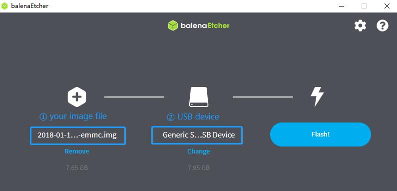
使用 Balena Etcher 写入镜像,支持 Windows、Linux 和 macOS。
Balena Etcher 是 Balena 提供的开源图形化镜像写入工具,可将操作系统镜像写入 SD 卡或 U 盘。
-
单击“Flash from file”选择镜像。
-
单击“Select target”选择目标设备。
-
单击“Flash!”开始写入。
-
-
使用 Balena CLI 写入镜像,支持 Windows、Linux 和 macOS。
Balena CLI 是 balenaCloud/openBalena 的命令行工具,可用于写入 Linux 镜像。从 balena-io Releases 下载安装程序或独立软件包,并按照 安装说明正确安装到 PC。随后可使用 Balena 的“local flash”命令将 Linux 镜像写入 SD 卡或 U 盘。
$ sudo balena local flash xxx-bpi-ai2n-xxx.img.xz $ sudo balena local flash xxx-bpi-ai2n-xxx.img.xz --drive /dev/sdX $ sudo balena local flash xxx-bpi-ai2n-xxx.img.xz --drive /dev/sdX --yes -
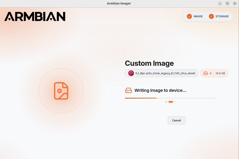
使用 Armbian Imager 写入镜像,支持 Windows、Linux 和 macOS。
Armbian Imager 是用于安装 Armbian OS 的开源镜像写入工具。
对于非官方开发板镜像,请依次选择 Use Custom Image → Browse,选择本地镜像文件和目标存储设备,再选择 Erase & Flash。
-
在 Linux 中使用 dd 命令写入镜像
如果 SD 卡设备 /dev/sdX 的分区已自动挂载,请先将其卸载。
$ sudo apt-get install xz-utils pv
$ sudo sh -c 'xzcat xxx-bpi-ai2n-xxx.img.xz | pv | dd of=/dev/sdX bs=1M status=progress && sync'
¶ 安装镜像到 eMMC
-
准备一张已写入 Linux 镜像的 SD 卡,并用该 SD 卡启动开发板。
-
将目标镜像复制到 U 盘,将 U 盘插入开发板并挂载。
-
将镜像安装到 eMMC。
-
使用 dd 命令写入。如果 mmcblk0p1 和 mmcblk0p2 分区已自动挂载,请先卸载。
$ sudo apt-get install xz-utils pv $ sudo sh -c 'xzcat xxx-bpi-ai2n-xxx.img.xz | pv | dd of=/dev/sdX bs=1M status=progress && sync' -
另一种方法是将 SD 卡上正在运行的 Armbian 系统迁移到 eMMC 等内部存储设备。该工具会准备目标存储、复制当前系统、调整引导加载程序设置,并确保系统无需重新安装即可独立启动。
$ sudo armbian-config --cmd STO001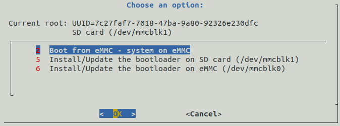
-
¶ 构建 Armbian 源代码
$ git clone -b bpi-v25.8.1 https://github.com/BPI-SINOVOIP/armbian-build.git
$ cd armbian-build
$ ./compile.sh BOARD=bpi-ai2n BRANCH=legacy有关 Armbian 构建的更多信息,请参阅 Armbian 构建框架快速入门指南。
¶ 首次启动
将 SD 卡插入插槽并给开发板上电。如果您通过 HDMI 连接显示器或连接到串行控制台,则首次启动时将自动登录。
登录后,系统会提示您更改默认密码。然后,系统会要求您创建一个具有 sudo 权限的普通用户帐户。请注意,此时键盘使用的是 QWERTY 布局。如果您没有有线网络连接并且检测到无线适配器,系统将提示您连接。
Welcome to Bananapi-Armbian!

Documentation: https://wiki.banana-pi.org/ | Community support: https://forum.banana-pi.org/

IP address:  Network connection timeout!

Create root password: ********
Repeat root password: ********

Warning: Weak password, it is based on a dictionary word!

Choose default system command shell:

1) bash
2) zsh
1

Shell: BASH

Creating a new user account. Press <Ctrl-C> to abort

Please provide a username (eg. your first name): pi
Create user (pi) password: ********
Repeat user (pi) password: ********

Warning: Weak password, it is based on a dictionary word!

Please provide your real name: Pi

Dear Pi, your account pi has been created and is sudo enabled.
Please use this account for your daily work from now on.

Internet connection was not detected.

Connect via wireless? [Y/n] y

Detected wireless networks:

1        NETWORK
2        MY-WIFI

Enter a number of SSID: 2

Enter a password for MY-WIFI: password

Probing internet connection (9)

Detected timezone: Asia/Shanghai

Set user language based on your location? [Y/n] Y

At your location, more locales are possible:

1) bo_CN                    4) ug_CN@latin
2) ug_CN                    5) zh_CN.UTF-8
3) ug_CN@latin              6) Skip generating locales
Please enter your choice:5

Generating locales: zh_CN.UTF-8

 | _ ) __ _ _ _  __ _ _ _  __ _ _ __(_)___ /_\  _ _ _ __ | |__(_)__ _ _ _
 | _ \/ _` | ' \/ _` | ' \/ _` | '_ \ |___/ _ \| '_| '  \| '_ \ / _` | ' \
 |___/\__,_|_||_\__,_|_||_\__,_| .__/_|  /_/ \_\_| |_|_|_|_.__/_\__,_|_||_|
                               |_|
 v25.5.1 for Banana Pi AI2N running Armbian Linux 6.1.107-legacy-renesas

 Packages:     Ubuntu stable (jammy), possible distro upgrade (noble)
 Support:      DIY (custom image)
 IPv4:         (LAN) 10.0.1.5 (WAN) 36.44.140.189

 Performance:

 Load:         35%              Up time:       17 min
 Memory usage: 3% of 7.01G
 CPU temp:     35�°C             Usage of /:   16% of 15G
 RX today:     265 KiB
 Commands:

 Configuration : armbian-config
 Monitoring    : htop

root@bpi-ai2n:/#这些设置也可以预先载入,详情请参阅 Armbian 自动配置。
¶ Armbian-Config
Armbian-Config 是用于配置开发板、调整服务和安装应用程序的工具,Armbian 镜像默认附带该工具。
使用以下命令启动 Armbian-Config:
$ sudo armbian-config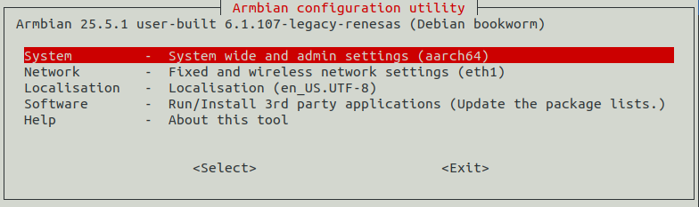
¶ 调试串口
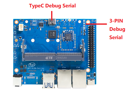
开发板提供两个调试串口:
-
Type-C 接口:使用普通 USB Type-C 线即可连接 PC,无需在 Linux 或 Windows 中安装专用驱动;波特率为 115200。
-
3 Pin 排针接口:标准 3.3 V TTL 电平 UART,需要 USB 转 TTL 串口线(如 CP2102、PL2303、CH340 等)连接 PC;波特率为 115200。
¶ 网络
Armbian 使用 Netplan.io 描述网络配置。Netplan 通过声明式配置简化 Linux 网络设置;如需手动配置网络,只需创建或编辑 Netplan YAML 文件(语法请参阅 Netplan 文档)。
-
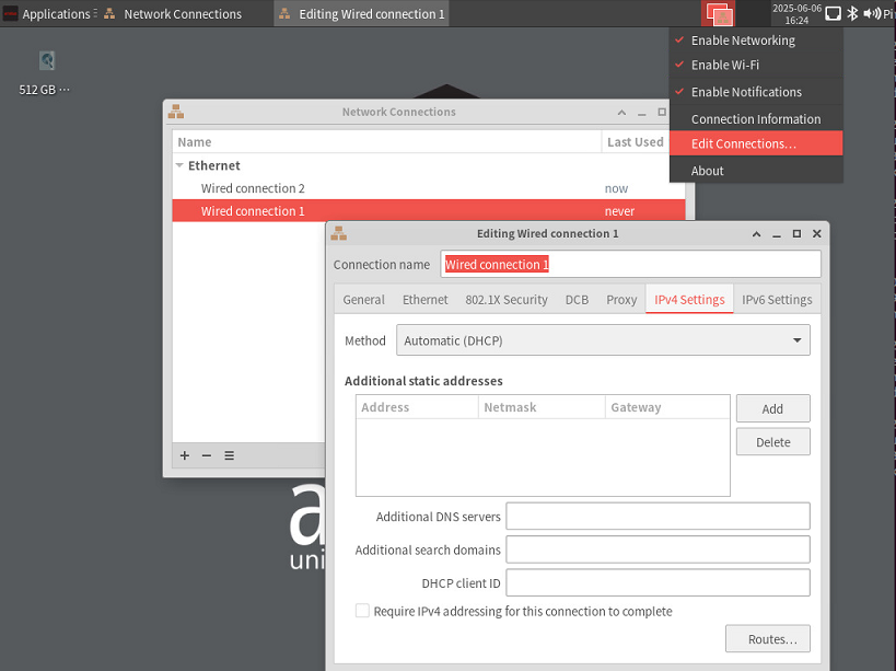
NetworkManager Applet 图形界面
对于桌面镜像,右键单击系统托盘中的 NetworkManager Applet 图标,再选择“Edit Connections”配置网络。
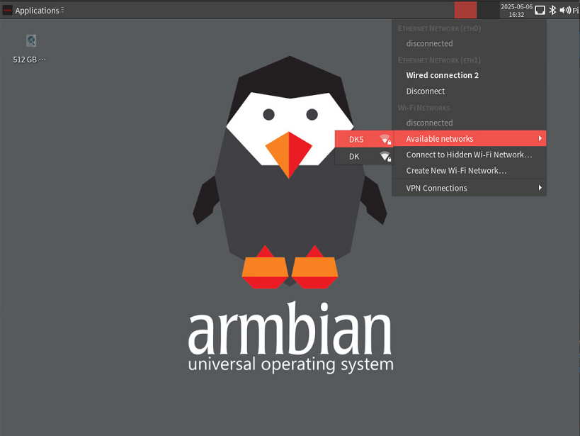
要连接无线网络,可左键单击系统托盘中的 NetworkManager Applet 图标,再选择可用网络项,显示无线网络列表。
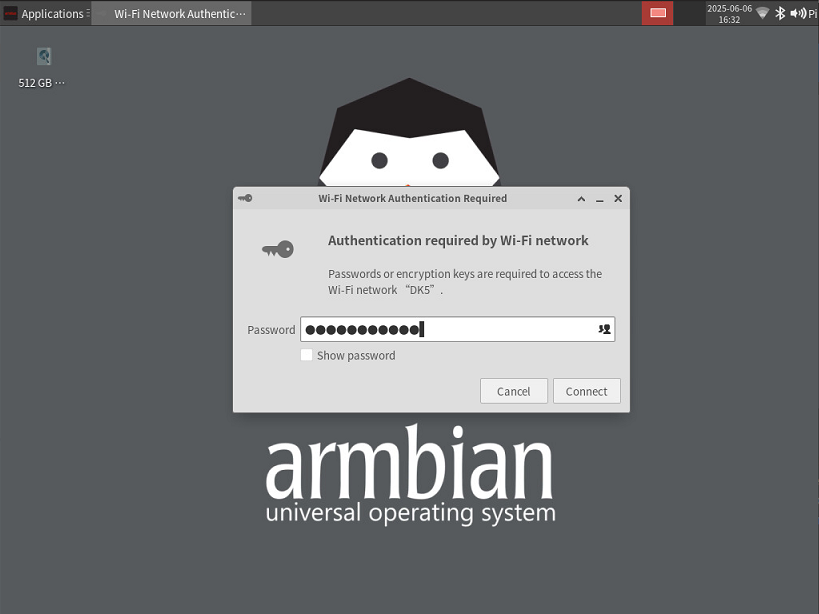
单击您要连接的网络。如果网络是安全的,则会出现一个对话框提示您输入网络密钥:
-
Netplan
桌面和 CLI 镜像均附带默认 Netplan YAML 文件 /etc/netplan/00-default-use-network-manager.yaml。这些镜像默认使用 NetworkManager 后端;所有以太网接口均配置为 DHCP,会自动从路由器获取 IP 地址。
# Added by Armbian # # Reference: https://netplan.readthedocs.io/en/stable/netplan-yaml/ # # Let NetworkManager manage all devices on this system. # Any device will come up with DHCP, once carrier is detected. # This is basically Netplan passing control over to NetworkManager at boot time. network: version: 2 renderer: NetworkManager如果首次启动时成功建立 Wi-Fi 连接,系统会创建 /etc/netplan/30-wifis-dhcp.yaml。若首次启动时未连接 Wi-Fi,也可在启动后手动创建该文件。
# Created by Armbian firstlogin script network: wifis: wlan0: dhcp4: yes dhcp6: yes access-points: "NETWORK": password: "password"有关 Netplan 配置的更多信息,请参阅 Netplan 文档。
修改 YAML 文件后,需要应用配置:
$ sudo chmod 600 /etc/netplan/xxx.yaml $ sudo netplan apply -
使用命令行配置无线连接
-
检查 Wi-Fi 无线功能是否已启用:
$ nmcli radio wifi如果该命令返回“enabled”,即可继续配置连接;如果返回“disabled”,请使用以下命令启用 Wi-Fi:
$ nmcli radio wifi on -
扫描无线网络
$ nmcli dev wifi list IN-USE BSSID SSID MODE CHAN RATE SIGNAL BARS SECURIT> F8:8C:21:8E:D7:A3 DK Infra 1 540 Mbit/s 64 *** WPA1 WP> FA:8C:21:AE:D7:A3 -- Infra 1 540 Mbit/s 64 *** WPA1 WP> FA:8C:21:AE:D7:A5 -- Infra 149 540 Mbit/s 42 ** WPA1 WP> F8:8C:21:8E:D7:A5 DK5 Infra 149 540 Mbit/s 40 ** WPA1 WP>在“SSID”列中查找您要连接的网络的名称。使用 SSID 和密码连接到网络。
-
连接到网络
运行以下命令配置网络连接,将 <example_ssid> 替换为目标网络名称。出现提示时输入网络密码,开发板随后应自动连接该网络。
$ sudo nmcli --ask dev wifi connect <example_ssid> Password: ************** Device 'wlan0' successfully activated with '639d32e7-6516-44a5-a538-f80ad7ebe177'. -
检查您是否已连接到网络
$ nmcli dev wifi list您应该看到类似于以下内容的输出:
$ nmcli dev wifi list
IN-USE  BSSID              SSID  MODE   CHAN  RATE        SIGNAL  BARS  SECURIT>
        FA:8C:21:AE:D7:A3  --    Infra  1     540 Mbit/s  67      ***   WPA1 WP>
        F8:8C:21:8E:D7:A3  DK    Infra  1     540 Mbit/s  64      ***   WPA1 WP>
*       F8:8C:21:8E:D7:A5  DK5   Infra  149   540 Mbit/s  39      **    WPA1 WP>
        FA:8C:21:AE:D7:A5  --    Infra  149   540 Mbit/s  39      **    WPA1 WP>
-
-
也可以在所有 Armbian 镜像中使用 armbian-config 配置网络。
$ sudo armbian-config --cmd BNS001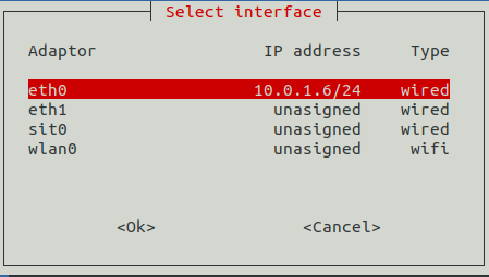
¶ 显示
RZ/V2N 芯片提供一个用于显示输出的 MIPI DSI 接口。我们为其开发了 DSI 转 HDMI 适配板和 7 英寸 HC070 触摸屏。
-
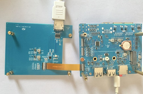
HDMI
使用 FPC 排线将 HDMI 转接板连接到载板的 MIPI DSI 接口,最高支持 1080p@60Hz。
-
LCD 面板
使用 FPC 排线将 Banana Pi 7 英寸 HC070 触摸屏连接到载板的 MIPI DSI 接口,并启用 panel-hc070iy30025 设备树 Overlay。
overlays=panel-hc070iy30025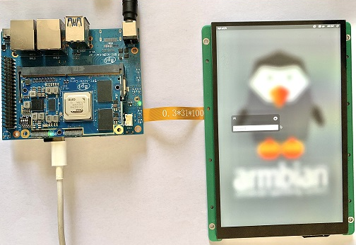
¶ RGB LED
开发板提供两个可由用户控制的 RGB LED。
-
载板上的黄色 LED,默认使用 heartbeat 触发器
$ sudo sh -c 'echo timer > /sys/class/leds/carrier-led/trigger' -
核心板上的蓝色 LED,默认使用 default-on 触发器
$ sudo sh -c 'echo none > /sys/class/leds/core-led/trigger'
¶ 风扇
通过 hwmon sysfs 接口控制风扇的开关状态。
-
启用风扇
$ sudo sh -c 'echo 1 > /sys/class/hwmon/hwmon3/fan1_target'-
禁用风扇
$ sudo sh -c 'echo 0 > /sys/class/hwmon/hwmon3/fan1_target'¶ ADC
RZ/V2N 内置 3 个 12 位 ADC 单元,每个单元最多支持 8 个通道。开发板的 ADC 排针 CN3 连接到 adc1。
通过 IIO sysfs 读取 ADC 数据:
$ cat /sys/bus/iio/devices/iio:device1/in_voltage0_raw¶ M.2 NVMe
开发板提供一个 PCIe 3.0 ×2 M.2 M Key 接口和标准 M.2 2280 固定孔,可安装 M.2 2280 NVMe SSD。
$ lspci
00:00.0 PCI bridge: Renesas Technology Corp. Device 1135
01:00.0 Non-Volatile memory controller: Kingston Technology Company, Inc. KC3000/FURY Renegade NVMe SSD [E18] (rev 01)可运行以下命令,通过 Pi Benchmarks 测试 SSD 性能:
$ wget https://raw.githubusercontent.com/TheRemote/PiBenchmarks/master/Storage.sh
$ chmod +x Storage.sh
$ sudo ./Storage.sh /path/to/storageSD 卡、eMMC 和 NVMe SSD(金士顿 SKC3000S512G)的测试结果如下:
类别 |
测试 |
SD 卡测试结果 |
eMMC 测试结果 |
NVMe SSD 测试结果 |
HDParm |
磁盘读取 |
12.20 MB/s |
47.37 MB/s |
760.69 MB/s |
HDParm |
缓存磁盘读取 |
12.49 MB/s |
41.18 MB/s |
730.07 MB/s |
DD |
磁盘写入 |
14.4 MB/s |
66.6 MB/s |
162 MB/s |
FIO |
4K 随机读取 |
2328 IOPS (9313 KB/s) |
6623 IOPS (26494 KB/s) |
54759 IOPS (219037 KB/s) |
FIO |
4K 随机写入 |
944 IOPS (3777 KB/s) |
6450 IOPS (25801 KB/s) |
25793 IOPS (103173 KB/s) |
IOZone |
4K 读取 |
11684 KB/s |
20569 KB/s |
94365 KB/s |
IOZone |
4K 写入 |
4969 KB/s |
19340 KB/s |
60732 KB/s |
IOZone |
4K 随机读取 |
8902 KB/s |
20556 KB/s |
40856 KB/s |
IOZone |
4K 随机写入 |
5135 KB/s |
23332 KB/s |
107290 KB/s |
得分:1371 |
得分:5146 |
得分:20342 |
¶ Wi-Fi
板载无线模块为 Realtek RTL8821CU,是一款支持 IEEE 802.11b/g/n/ac(1T1R)的 USB 2.0 Wi-Fi/蓝牙模块。
$ ifconfig  wlan0
wlan0: flags=4163<UP,BROADCAST,RUNNING,MULTICAST>  mtu 1500
        inet 10.0.1.12  netmask 255.255.255.0  broadcast 10.0.1.255
        inet6 fe80::44a5:d624:e8e0:2bea  prefixlen 64  scopeid 0x20<link>
        ether 14:5d:34:49:97:8e  txqueuelen 1000  (Ethernet)
        RX packets 4343  bytes 838419 (818.7 KiB)
        RX errors 0  dropped 0  overruns 0  frame 0
        TX packets 507  bytes 41012 (40.0 KiB)
TX errors 0 dropped 0 overruns 0 carrier 0 collisions 0Wi-Fi 配置详情请参阅“网络”章节。
¶ 蓝牙
板载蓝牙模块为 Realtek RTL8821CU。其蓝牙控制器支持 Bluetooth 4.2,并兼容 Bluetooth 2.1 + EDR。
$ hcitool dev
Devices:
hci0 14:5D:34:49:97:8F可使用 blueman-manager 或 bluetoothctl 命令行工具管理蓝牙适配器。
-
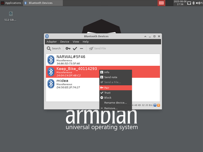
在桌面镜像中通过 Blueman 使用蓝牙
右键单击系统托盘中的蓝牙图标,然后在蓝牙设备窗口中选择设备项。
-
通过 bluetoothctl 命令使用蓝牙
安装 BlueZ:
$ sudo apt install bluez启动蓝牙控制台:
$ bluetoothctl
[bluetooth]# list
Controller 14:5D:34:49:97:8F bpi-ai2n [default]
[bluetooth]# power on
Changing power on succeeded
[bluetooth]# agent on
Agent is already registered
[bluetooth]# default-agent
Default agent request successful
[bluetooth]# discoverable on
Changing discoverable on succeeded
[CHG] Controller 14:5D:34:49:97:8F Discoverable: yes
[bluetooth]# pairable on
Changing pairable on succeeded
[bluetooth]# scan on
Discovery started
[CHG] Controller 14:5D:34:49:97:8F Discovering: yes
[NEW] Device 77:2B:0B:D7:28:A5 77-2B-0B-D7-28-A5
[NEW] Device 42:66:40:6D:8B:6F 42-66-40-6D-8B-6F
[NEW] Device 24:0A:C4:DF:4B:C2 Keep_Bike_40114293
[NEW] Device 34:86:5D:73:5F:46 NARWAL#5F46
[CHG] Device 24:0A:C4:DF:4B:C2 ServiceData Key: 00001818-0000-1000-8000-00805f9b34fb
[bluetooth]# pair TargetDeviceMac
¶ 相机
¶ Type-C OTG
USB Type-C 端口仅支持 Device 模式。
¶ DTB Overlay
DTB Overlay 用于配置 40 Pin GPIO 的复用功能。
pi@bpi-ai2n:/boot/dtb/renesas/overlay$ ls bpi-ai2n*
bpi-ai2n-i2c0-mux.dtbo               bpi-ai2n-spi0.dtbo
bpi-ai2n-i2c1.dtbo                   bpi-ai2n-spi2.dtbo
bpi-ai2n-i2c1-flash.dtbo             bpi-ai2n-spi2-flash.dtbo
bpi-ai2n-i2c1-rtc.dtbo               bpi-ai2n-spi2-waveshare-st7789v.dtbo
bpi-ai2n-i2c2.dtbo                   bpi-ai2n-spi2-waveshare-tft24.dtbo
bpi-ai2n-i2s3-nxez-pcm512x.dtbo      bpi-ai2n-spi2-waveshare-tft35c.dtbo
bpi-ai2n-i2s3-waveshare-wm8960.dtbo  bpi-ai2n-uart0.dtbo
bpi-ai2n-pwm.dtbo                    bpi-ai2n-uart2.dtbo
bpi-ai2n-pwmfan.dtbo使用 armbian-config 图形化工具配置 Overlay:
$ sudo armbian-config --cmd DTO001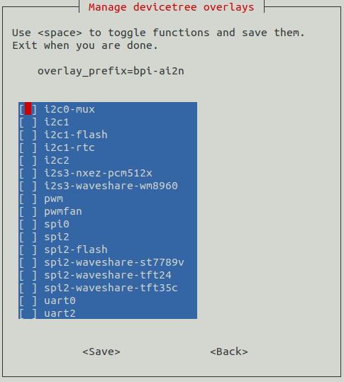
也可以在 /boot/armbianEnv.txt 的 overlays= 行中添加要启用的 Overlay 名称,名称之间以空格分隔。例如,启用 i2c1、spi2 和 uart0:
overlays=i2c1 spi2 uart0重启开发板以应用 Overlay 配置。
¶ GPIO
过去,Linux 内核通过 /sys/class/gpio 命名空间公开 GPIO 引脚,但该接口自 4.8 版本起已弃用。替代方案是名为 libgpiod 的 C 库及一组名为 gpiod 的用户空间工具。
-
安装 gpiod
$ sudo apt install gpiod -
列出 GPIO 芯片
输出各芯片的标签和 GPIO 线数量。芯片可通过编号、名称或路径标识,例如“0”“gpiochip0”和“/dev/gpiochip0”均指向同一个芯片。
$ sudo gpiodetect gpiochip0 [10410000.pinctrl] (96 lines) -
列出 GPIO 线
输出 GPIO 线信息。GPIO 线可按名称指定;提供芯片选项时,也可按偏移量指定。每条 GPIO 线对应一个 GPIO 引脚,该引脚的全局 GPIO 编号为线偏移量加 416。
$ sudo gpioinfo gpiochip0 - 96 lines: line 0: "P00" "carrier-led" output active-high [used] line 1: "P01" "core-led" output active-high [used] line 2: "P02" unused input active-high line 3: "P03" "interrupt" input active-high [used] ... line 93: "PB5" unused input active-high line 94: "PB6" unused input active-high line 95: "PB7" unused input active-high -
根据 GPIO 名称获取线偏移量。例如,40 Pin 排针的物理 Pin 31 名为 P9_5。
$ sudo gpiofind P9_5 77 -
读取 40 Pin 排针物理 Pin 31 的值
$ sudo gpioget gpiochip0 77 1 -
将 40 Pin 排针物理 Pin 31 设置为低电平
$ sudo gpioset gpiochip0 77=0 -
监视 GPIO 电平变化事件。使用 -r 监视上升沿,或使用 -f 监视下降沿,但两者不能同时指定。
$ sudo gpiomon -r gpiochip0 77
event:  RISING EDGE offset: 77 timestamp: [   22813.801682561]
¶ Python3-gpiod
python3-gpiod 是 libgpiod 的 Python 绑定,可通过 Python 控制 GPIO 线。
-
安装 python3-libgpiod
$ sudo apt install python3-libgpiod -
以下示例代码读取 40 Pin 排针物理 Pin 31 的状态。
import gpiod # 40pin, phy pin.31 LINE_OFFSET = 77 chip = gpiod.Chip("0", gpiod.Chip.OPEN_BY_NUMBER) line = chip.get_line(LINE_OFFSET) line.request(consumer='gpio', type=gpiod.LINE_REQ_DIR_IN) value = line.get_value() print(f"GPIO value is {value}") -
以下示例代码控制连接到 40 Pin 排针物理 Pin 31 的 LED。
import time import gpiod # 40pin, phy pin.31 LINE_OFFSET = 77 chip = gpiod.Chip("0", gpiod.Chip.OPEN_BY_NUMBER) line = chip.get_line(LINE_OFFSET) line.request(consumer="gpio", type=gpiod.LINE_REQ_DIR_OUT, default_vals=[0]) try: while True: line.set_value(1) time.sleep(0.5) line.set_value(0) time.sleep(0.5) finally: line.set_value(1) line.release() -
以下示例代码读取连接到 40 Pin 排针物理 Pin 3 的按钮状态,并在按下按钮时点亮连接到物理 Pin 31 的 LED:
import gpiod

# 40pin, phy pin.31
LED_LINE_OFFSET = 77

# 40pin, phy pin.3
BUTTON_LINE_OFFSET = 26

chip_led = gpiod.Chip("0", gpiod.Chip.OPEN_BY_NUMBER)
chip_button = gpiod.Chip("0", gpiod.Chip.OPEN_BY_NUMBER)

line_led = chip_led.get_line(LED_LINE_OFFSET)
line_led.request(consumer="LED", type=gpiod.LINE_REQ_DIR_OUT, default_vals=[0])

line_button = chip_button.get_line(BUTTON_LINE_OFFSET)
line_button.request(consumer="BUTTON", type=gpiod.LINE_REQ_DIR_IN)

try:
    while True:
        line_led.set_value(line_button.get_value())
finally:
    line_led.set_value(1)
    line_led.release()
    line_button.release()
¶ Python3-periphery
python-periphery 是一个纯 Python 库,用于在 Linux 用户空间访问 GPIO、LED、PWM、SPI、I2C、MMIO 和串口等外设 I/O 接口。
使用 40 Pin 排针上的总线控制器前,必须启用相应的 DTB Overlay。
-
安装 python3-periphery
$ sudo apt install python3-periphery -
以下示例代码读取 40 Pin 排针物理 Pin 31 的状态。
from periphery import GPIO # 40pin, phy pin.31 CHIP = "/dev/gpiochip0" LINE_OFFSET = 77 gpio = GPIO(CHIP, LINE_OFFSET, "out") gpio.write(True) print("GPIO state:", gpio.read()) gpio.close() -
以下示例代码控制连接到 40 Pin 排针物理 Pin 31 的 LED。
import time from periphery import GPIO # 40pin, phy pin.31 CHIP = "/dev/gpiochip0" LINE_OFFSET = 77 gpio = GPIO(CHIP, LINE_OFFSET, "out") gpio.write(False) try: while True: gpio.write(True) time.sleep(0.5) gpio.write(False) time.sleep(0.5) finally: gpio.write(False) gpio.close() -
以下示例代码读取连接到 40 Pin 排针物理 Pin 3 的按钮状态,并在按下按钮时点亮连接到物理 Pin 31 的 LED:
from periphery import GPIO # 40pin, phy pin.31 LED_CHIP = "/dev/gpiochip0" LED_LINE_OFFSET = 77 # 40pin, phy pin.3 BUTTON_CHIP = "/dev/gpiochip0" BUTTON_LINE_OFFSET = 26 led = GPIO(LED_CHIP, LED_LINE_OFFSET, "out") button = GPIO(BUTTON_CHIP, BUTTON_LINE_OFFSET, "in") try: while True: print(button.read()) led.write(button.read()) finally: led.write(True) led.close() button.close() -
以下示例代码从地址为 0x50 的设备读取寄存器 0x00 的值。该设备连接到 40 Pin 排针物理 Pin 3 和 Pin 5 上的 I2C1;请先启用 i2c1 DTB Overlay。
from periphery import I2C I2C_DEV = "/dev/i2c-1" SLAVE_ADDR = 0x50 i2c = I2C(I2C_DEV) msg = [I2C.Message([0x10]), I2C.Message([0x00], read=True)] i2c.transfer(SLAVE_ADDR, msg) print("I2C data read: 0x{:02x}".format(msg[1].data[0])) i2c.close() -
以下示例代码执行 SPI 环回测试。请将 40 Pin 排针物理 Pin 19(SPI2_MOSI)直接连接到物理 Pin 21(SPI2_MISO)。测试前需要加载 spidev 驱动模块并启用 spi2 DTB Overlay。
from periphery import SPI SPI_DEV = "/dev/spidev2.0" data_out = [0xAA, 0xBB, 0xCC, 0xDD] try: spi = SPI(SPI_DEV, 0, 1000000) data_in = spi.transfer(data_out) print("Send Data: [0x{:02x}, 0x{:02x}, 0x{:02x}, 0x{:02x}]".format(*data_out)) print("Receive Data: [0x{:02x}, 0x{:02x}, 0x{:02x}, 0x{:02x}]".format(*data_in)) finally: spi.close() -
以下示例代码通过 UART 向连接在 40 Pin 排针物理 Pin 8(UART2_TXD)和 Pin 10(UART2_RXD)上的设备发送数据。测试前需要启用 uart2 DTB Overlay。
from periphery import Serial

UART_DEV = "/dev/ttySC2"
BAUDRATE = 115200

serial = Serial(UART_DEV, BAUDRATE)
serial.write(b"Hello, World!\n")

serial.close()
¶ Adafruit Blinka
Adafruit Blinka 是一个兼容层,将 CircuitPython 硬件 API 带到使用 Python 3 的 Linux 系统,便于操作传感器、显示屏等 I2C/SPI/UART 设备。更多信息请参阅 Adafruit Learning System 和 Adafruit GitHub。
该项目已支持 RZ/V2N 芯片和 BPI-AI2N。使用 40 Pin 排针上的总线控制器前,必须启用相应的 DTB Overlay。
-
安装软件包
$ sudo apt install git gpiod python3-dev python3-libgpiod python3-periphery python3-pip python3-venv libjpeg-dev zlib1g-dev libfreetype-dev libfreetype6 fonts-dejavu -
创建项目,并在其中安装 Python 虚拟环境。
$ sudo su # mkdir project # cd project # python3 -m venv myenv # source myenv/bin/activate (myenv) root@bpi-ai2n:~/project# -
安装 gpiod Python 绑定库
(myenv) root@bpi-ai2n:~/project# pip3 install gpiod -
在虚拟环境中安装 Adafruit Blinka
-
从 PyPI 安装。
(myenv) root@bpi-ai2n:~/project# pip3 install Adafruit-Blinka -
从 Git 源码安装
(myenv) root@bpi-ai2n:~/project# pip3 install git+https://github.com/adafruit/Adafruit_Blinka
-
-
Blinka 测试
-
示例 test_blinka.py 用于验证 Adafruit-Blinka 是否安装正确。运行测试前,请加载 spidev 驱动模块,并启用 i2c1 和 spi2 DTB Overlay。
import board import digitalio import busio print("Hello, blinka!") # pin.31, Try to create a Digital input pin = digitalio.DigitalInOut(board.D31) print("Digital IO ok!") # Try to create an I2C device i2c = busio.I2C(board.SCL, board.SDA) print("I2C ok!") # Try to create an SPI device spi = busio.SPI(board.SCLK, board.MOSI, board.MISO) print("SPI ok!") print("done!")该示例的运行结果如下:
(myenv) root@bpi-ai2n:~/project# python3 test_blinka.py Hello, blinka! Digital IO ok! I2C ok! SPI ok! done! -
以下示例代码控制连接到 40 Pin 排针物理 Pin 31 的 LED。
import time import board import digitalio print("hello blinky!") # pin.31 led = digitalio.DigitalInOut(board.D31) led.direction = digitalio.Direction.OUTPUT while True: led.value = True time.sleep(0.5) led.value = False time.sleep(0.5) -
以下示例代码读取连接到 40 Pin 排针物理 Pin 3 的按钮状态,并在按下按钮时点亮连接到物理 Pin 31 的 LED:
import time import board import digitalio print("press the button!") # pin.31 led = digitalio.DigitalInOut(board.D31) led.direction = digitalio.Direction.OUTPUT # pin.3 button = digitalio.DigitalInOut(board.D3) button.direction = digitalio.Direction.INPUT button.pull = digitalio.Pull.UP while True: led.value = not button.value -
使用 MCP23017 I2C LCD1602 模块测试 I2C RGB LCD
从 Git 仓库安装库。这两个仓库分别派生自 Adafruit_CircuitPython_CharLCD 和 Adafruit_CircuitPython_MCP230xx,并已按 MCP23017 I2C LCD1602 模块的硬件进行修改。两个仓库中的示例也应根据硬件设计作相应调整。
(myenv) root@bpi-ai2n:~/project# pip3 install git+https://github.com/Dangku/Adafruit_CircuitPython_CharLCD (myenv) root@bpi-ai2n:~/project# pip3 install git+https://github.com/Dangku/Adafruit_CircuitPython_MCP230xx运行测试示例:
(myenv) root@bpi-ai2n:~/project# wget https://raw.githubusercontent.com/Dangku/Adafruit_CircuitPython_CharLCD/main/examples/charlcd_i2c_rgb_simpletest.py
(myenv) root@bpi-ai2n:~/project# python3 charlcd_i2c_rgb_simpletest.py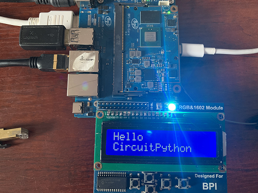
-
使用 SSD1306 SPI OLED 模块进行 SPI OLED 测试
从 Git 仓库安装库。该仓库派生自 Adafruit_CircuitPython_SSD1306,库和示例已按 SSD1306 SPI OLED 模块的硬件进行修改。
(myenv) root@bpi-ai2n:~/project# pip3 install git+https://github.com/Dangku/Adafruit_CircuitPython_SSD1306部分导入 PIL 的示例需要安装 Pillow。直接执行 pip3 install Pillow 会出现“ImportError: cannot import name '_imagingft' from 'PIL'”,因此请改用以下命令:
(myenv) root@bpi-ai2n:~/project# pip3 install Pillow --no-binary :all:运行测试示例:
(myenv) root@bpi-ai2n:~/project# wget https://raw.githubusercontent.com/Dangku/Adafruit_CircuitPython_SSD1306/main/examples/ssd1306_stats.py
(myenv) root@bpi-ai2n:~/project# python3 ssd1306_stats.py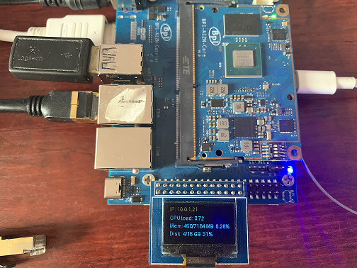
-
使用 SSD1306 I2C OLED 模块进行 I2C OLED 测试
库和示例源码与 SPI SSD1306 相同,但必须修改示例以启用 I2C 接口并禁用 SPI 接口。
# Create the I2C interface. i2c = board.I2C() # Create the SSD1306 OLED class. # The first two parameters are the pixel width and pixel height. Change these # to the right size for your display! disp = adafruit_ssd1306.SSD1306_I2C(WIDTH, HEIGHT, i2c) # Use for SPI #spi = board.SPI() # disp_cs = digitalio.DigitalInOut(board.CS) #disp_cs = None #disp_dc = digitalio.DigitalInOut(board.D18) #disp_reset = digitalio.DigitalInOut(board.D22) #disp = adafruit_ssd1306.SSD1306_SPI(WIDTH, HEIGHT, spi, disp_dc, disp_reset, dii sp_cs)运行测试示例:
(myenv) root@bpi-ai2n:~/project# python3 ssd1306_stats.py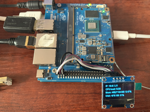
-
¶ WiringPi
构建并安装 WiringPi。在 Debian 上构建之前,必须先安装 sudo。
 $ sudo apt-get update
 $ sudo apt-get install build-essential git
 $ git clone https://github.com/Dangku/WiringPi
 $ cd WiringPi
 $ chmod a+x build
$ sudo ./build运行 gpio readall,显示全部 40 Pin 引脚的状态。
 $ sudo gpio readall
 +-----+-----+---------+------+---+-- AI2N --+---+------+---------+-----+-----+
 | I/O | wPi |   Name  | Mode | V | Physical | V | Mode |  Name   | wPi | I/O |
 +-----+-----+---------+------+---+----++----+---+------+---------+-----+-----+
 |     |     |    3.3V |      |   |  1 || 2  |   |      | 5V      |     |     |
 | 442 |   8 |   SDA.1 | HI-Z | 0 |  3 || 4  |   |      | 5V      |     |     |
 | 443 |   9 |   SCL.1 | HI-Z | 0 |  5 || 6  |   |      | 0V      |     |     |
 | 484 |   7 |  IO.484 | HI-Z | 0 |  7 || 8  | 0 | HI-Z | TxD2    | 15  | 460 |
 |     |     |      0V |      |   |  9 || 10 | 0 | HI-Z | RxD2    | 16  | 461 |
 | 488 |   0 |  IO.488 | HI-Z | 0 | 11 || 12 | 0 | HI-Z | IO.426  | 1   | 426 |
 | 489 |   2 |  IO.489 | HI-Z | 0 | 13 || 14 |   |      | 0V      |     |     |
 | 490 |   3 |  IO.490 | HI-Z | 0 | 15 || 16 | 0 | HI-Z | IO.463  | 4   | 463 |
 |     |     |    3.3V |      |   | 17 || 18 | 0 | HI-Z | IO.462  | 5   | 462 |
 | 508 |  12 |    MOSI | HI-Z | 0 | 19 || 20 |   |      | 0V      |     |     |
 | 507 |  13 |    MISO | HI-Z | 0 | 21 || 22 | 0 | HI-Z | IO.459  | 6   | 459 |
 | 509 |  14 |    SLCK | HI-Z | 0 | 23 || 24 | 0 | HI-Z | SS      | 10  | 503 |
 |     |     |      0V |      |   | 25 || 26 | 0 | HI-Z | IO.502  | 11  | 502 |
 | 432 |  30 |   SDA.2 | HI-Z | 0 | 27 || 28 | 0 | HI-Z | SCL.2   | 31  | 433 |
 | 491 |  21 |  IO.491 | HI-Z | 0 | 29 || 30 |   |      | 0V      |     |     |
 | 493 |  22 |  IO.493 | HI-Z | 0 | 31 || 32 | 0 | HI-Z | IO.456  | 26  | 456 |
 | 458 |  23 |  IO.458 | HI-Z | 0 | 33 || 34 |   |      | 0V      |     |     |
 | 427 |  24 |  IO.427 | HI-Z | 0 | 35 || 36 | 0 | HI-Z | IO.457  | 27  | 457 |
 | 495 |  25 |  IO.495 | HI-Z | 0 | 37 || 38 | 0 | HI-Z | IO.429  | 28  | 429 |
 |     |     |      0V |      |   | 39 || 40 | 0 | HI-Z | IO.420  | 29  | 420 |
 +-----+-----+---------+------+---+----++----+---+------+---------+-----+-----+
 | I/O | wPi |   Name  | Mode | V | Physical | V | Mode |  Name   | wPi | I/O |
+-----+-----+---------+------+---+-- AI2N --+---+------+---------+-----+-----+将 40 Pin 排针物理 Pin 31 设置为高电平或低电平,其 wPi 编号为 22。
 $ sudo gpio mode 22 out
 $ sudo gpio write 22 1
$ sudo gpio write 22 0BPI GPIO 扩展板示例位于 WiringPi/examples。
-
blinkall:不使用扩展板,闪烁连接到所有 GPIO 引脚的 LED。
-
lcd-adafruit:BPI LCD 1602 显示模块
-
oled:BPI OLED 显示模块
-
ssd1306/oled: 0.96" I2C SSD1306 OLED
-
matrixled:BPI RGB LED 矩阵扩展模块
-
berryclip:BPI BerryClip 模块
| 此 WiringPi 仅支持将 40 Pin GPIO 配置为输出或输入。若要使用 I2C、SPI、PWM 等复用功能,必须启用相应的 DTB Overlay。 |
¶ RPi.GPIO
构建并安装。
 $ sudo apt-get update
 $ sudo apt-get install build-essential python3 python3-pip python3-dev python3-setuptools git
 $ git clone https://github.com/Dangku/RPi.GPIO.git
 $ cd RPi.GPIO
 $ sudo python3 setup.py clean --all
$ sudo python3 setup.py install创建并安装 wheel 软件包:
 $ sudo python3 setup.py bdist_wheel
$ sudo pip3 install dist/RPi.GPIO-XXX.whl也可以直接从 Git 源码安装,无需进入开发模式:
$ sudo pip3 install git+https://github.com/Dangku/RPi.GPIO.git如果该软件包已安装,则应在安装新软件包之前将其卸载,或者使用 --force-reinstall 选项安装新软件包。
-
以下示例代码控制连接到 40 Pin 排针物理 Pin 31 的 LED。
import RPi.GPIO as GPIO
import time
import sys

# phy pin.31, bcm pin.6
bcmledpin = 6
phyledpin = 31

def setup_bcm():
  GPIO.setmode(GPIO.BCM)
  GPIO.setup(bcmledpin, GPIO.OUT)

def setup_board():
  GPIO.setmode(GPIO.BOARD)
  GPIO.setup(phyledpin, GPIO.OUT)

def blink_bcm():
  while True:
    GPIO.output(bcmledpin, GPIO.HIGH)
    print("********set bcm pin ", bcmledpin, " High********")
    time.sleep(1)
    GPIO.output(bcmledpin, GPIO.LOW)
    print("********set bcm pin ", bcmledpin, " Low********")
    time.sleep(1)

def blink_board():
  while True:
    GPIO.output(phyledpin, GPIO.HIGH)
    print("********set phy pin ", phyledpin, " High********")
    time.sleep(1)
    GPIO.output(phyledpin, GPIO.LOW)
    print("********set phy pin ", phyledpin, " Low********")
    time.sleep(1)

def shutdown():
    GPIO.cleanup()

if __name__ == '__main__':     # Program start
  print('To read output correctly, jumper pin 13 (bcm27) to pin 31 (bcm6)')
  print('Press Ctrl-C to exit')
  setup_bcm()
  #setup_board()
  print("Hardware information: ", GPIO.RPI_INFO)
  try:
    blink_bcm()
    #blink_board()
  except KeyboardInterrupt:
    shutdown()
¶ WiringPi-Python
构建并安装。
 $ sudo apt-get update
 $ sudo apt-get install build-essential python3 python3-dev python3-setuptools swig git
 $ git clone --recursive  https://github.com/Dangku/WiringPi-Python.git
 $ cd WiringPi-Python
$ sudo python3 setup.py install-
以下示例代码控制连接到 40 Pin 排针物理 Pin 31 的 LED。
#!/usr/bin/env python

import wiringpi as wpi
import time

# phy pin.31, wPi pin.22
PIN = 22

wpi.wiringPiSetup()
wpi.pinMode(PIN, 1)

while True:
    wpi.digitalWrite(PIN, 1)
    time.sleep(1)
    wpi.digitalWrite(PIN, 0)
    time.sleep(1)
¶ 安装 Docker Engine
使用以下简单命令 安装 Docker Engine:
$ curl -sSL get.docker.com | sudo sh也可以使用 armbian-config 安装 Docker Engine:
$ armbian-config --cmd CON002运行 hello-world 镜像,验证 Docker Engine 是否安装正确。
 $ sudo docker run hello-world
 Unable to find image 'hello-world:latest' locally
 latest: Pulling from library/hello-world
 c9c5fd25a1bd: Pull complete
 Digest: sha256:0b6a027b5cf322f09f6706c754e086a232ec1ddba835c8a15c6cb74ef0d43c29
 Status: Downloaded newer image for hello-world:latest

 Hello from Docker!
 This message shows that your installation appears to be working correctly.

 To generate this message, Docker took the following steps:
  1. The Docker client contacted the Docker daemon.
  2. The Docker daemon pulled the "hello-world" image from the Docker Hub.
     (arm64v8)
  3. The Docker daemon created a new container from that image which runs the
     executable that produces the output you are currently reading.
  4. The Docker daemon streamed that output to the Docker client, which sent it
     to your terminal.

 To try something more ambitious, you can run an Ubuntu container with:
  $ docker run -it ubuntu bash

 Share images, automate workflows, and more with a free Docker ID:
  https://hub.docker.com/

 For more examples and ideas, visit:
https://docs.docker.com/get-started/¶ 远程访问
有时需要在不连接显示器、键盘和鼠标的情况下访问开发板。若要从局域网内的另一台设备远程控制 Banana Pi,可使用以下服务之一:
-
SSH
-
VNC
启用远程访问前,请先查找开发板的 IP 地址。
-
桌面
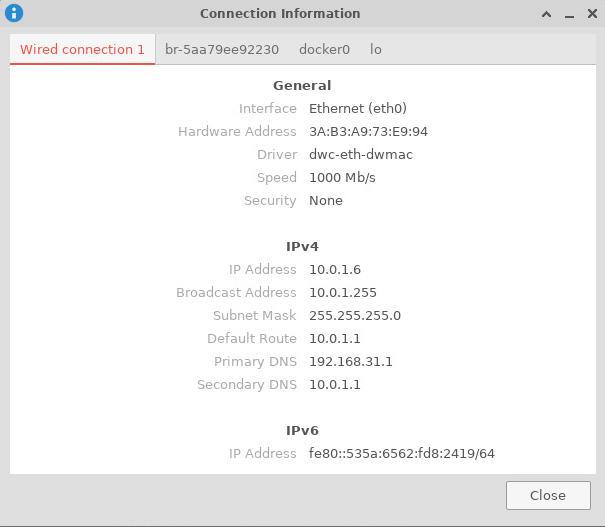
右键单击系统托盘中的 NetworkManager Applet 图标,再单击“Connection Information”,弹出窗口会显示全部网络信息。
-
命令行
运行以下命令将您的 IP 地址输出到命令行:
 $ hostname -I
10.0.1.6¶ SSH
在计算机上打开终端并输入以下命令,将 <ip address> 替换为目标 Banana Pi 的 IP 地址,将 <username> 替换为您的用户名:
$ ssh <username>@<ip address>¶ VNC
-
安装 x11vnc
$ sudo apt install x11vnc -
创建密码文件
$ x11vnc -storepasswd Enter VNC password: Verify password: Write password to /home/pi/.vnc/passwd? [y]/n y Password written to: /home/pi/.vnc/passwd -
创建服务文件 /lib/systemd/system/x11-vnc.service
[Unit] Description="x11vnc" Requires=display-manager.service After=lightdm.service [Service] ExecStart=/usr/bin/x11vnc -auth guess -loop -forever -safer -shared -ultrafilexfer -bg -o /var/log/x11vnc.log ExecStop=/usr/bin/killall x11vnc [Install] WantedBy=multi-user.target -
启用服务
sudo systemctl daemon-reload sudo systemctl enable x11-vnc sudo systemctl start x11-vnc -
连接 VNC 服务器
在客户端设备上安装并启动 TigerVNC:
 $ sudo apt install tigervnc-viewer
 $ vncviewer 10.0.1.6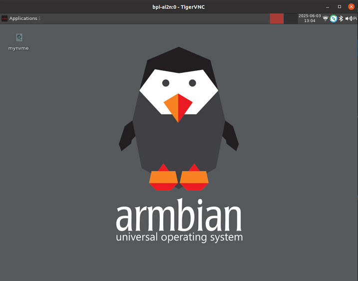
¶ 系统本地化
使用 armbian-config 工具修改系统时区、语言、键盘布局和主机名。
$ sudo armbian-config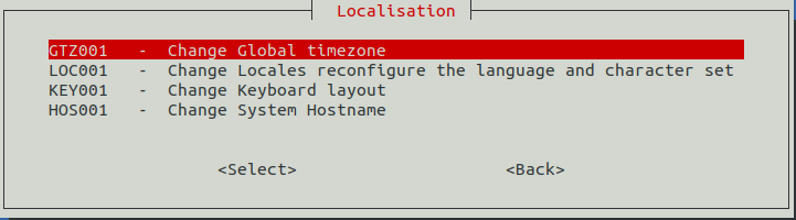
¶ Yocto AI SDK
¶ 准备
-
Yocto 镜像支持从 SD 卡或 eMMC 启动。
-
建议使用容量至少为 16 GB 的 A1 等级存储卡。
-
若要从 SD 卡启动 Yocto,请先格式化带有可启动系统的 eMMC。
-
下载最新的 Yocto 镜像,并确认校验值正确。
-
root 登录无需密码。
¶ 将 Yocto 镜像写入 SD 卡
-
使用 Balena Etcher 写入镜像,支持 Windows、Linux 和 macOS。
Balena Etcher 是 Balena 提供的开源图形化镜像写入工具,可将操作系统镜像写入 SD 卡或 U 盘。
-
单击“Flash from file”选择镜像。
-
单击“Select target”选择目标设备。
-
单击“Flash!”开始写入。
-
-
使用 Balena CLI 写入镜像,支持 Windows、Linux 和 macOS。
Balena CLI 是 balenaCloud/openBalena 的命令行工具,可用于写入 Linux 镜像。从 balena-io Releases 下载安装程序或独立软件包,并按照 安装说明正确安装到 PC。随后可使用 Balena 的“local flash”命令将 Linux 镜像写入 SD 卡或 U 盘。
$ sudo balena local flash core-image-weston-bananapi-ai2n-xxx.rootfs.wic.gz $ sudo balena local flash core-image-weston-bananapi-ai2n-xxx.rootfs.wic.gz --drive /dev/sdX $ sudo balena local flash core-image-weston-bananapi-ai2n-xxx.rootfs.wic.gz --drive /dev/sdX --yes -
使用 Armbian Imager 写入镜像,支持 Windows、Linux 和 macOS。
Armbian Imager 是用于安装 Armbian OS 的开源镜像写入工具。
对于非官方开发板镜像,请依次选择 Use Custom Image → Browse,选择本地镜像文件和目标存储设备,再选择 Erase & Flash。
-
在 Linux 中使用 dd 命令写入镜像
如果 SD 卡设备 /dev/sdX 的分区已自动挂载,请先将其卸载。
 $ sudo apt-get install gunzip pv
 $ sudo sh -c 'gunzip -c core-image-weston-bananapi-ai2n-xxx.rootfs.wic.gz | pv | dd of=/dev/sdX bs=1M status=progress && sync'
¶ 将 Yocto 镜像安装到 eMMC
-
准备一张已写入 Linux 镜像的 SD 卡,并用该 SD 卡启动开发板。
-
将 Linux 镜像复制到 U 盘,将 U 盘插入开发板并挂载。
-
使用 dd 命令安装。如果 mmcblk0p1 和 mmcblk0p2 分区已自动挂载,请先卸载。
 $ sudo apt-get install gunzip pv
 $ sudo sh -c 'gunzip -c core-image-weston-bananapi-ai2n-xxx.rootfs.wic.gz | pv | dd of=/dev/sdX bs=1M status=progress && sync'
¶ 其他开发
¶ 写入 SPI 引导加载程序
SPI 引导加载程序由三部分组成:Flash Writer 文件、ATF 固件和 U-Boot。对应文件为 Flash_Writer*.mot、bl2_bp_spi.srec(bl2_bp_spi.bin)和 fip.srec(fip.bin),可在 Linux 镜像的 /boot 目录中找到。
-
通过串口写入引导加载程序
-
将 Flash_Writer*.mot、bl2_bp_spi.srec 和 fip.srec 复制到 Windows PC。
-
使用 USB 线将 Windows PC 连接到核心板下方的 USB Type-C UART 端口。
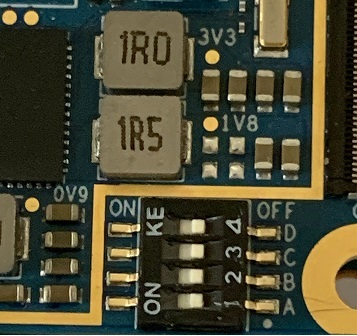
-
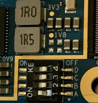
将 Bootsel 开关切换到 SCIF 下载模式。
-
在 Windows PC 上打开终端模拟器。以下以 Tera Term 4.108 为例。
如果使用 Tera Term 5.x,请在 Send file 窗口中选择“Send in same way as Tera Term 4”。 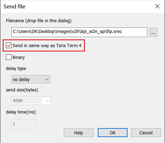
-
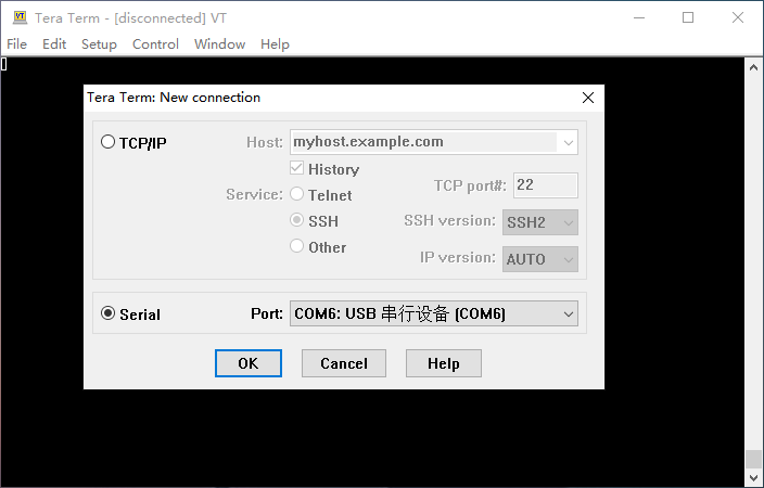
选择“文件”>“新建连接”,然后选择“串行”端口,如下所示。
-
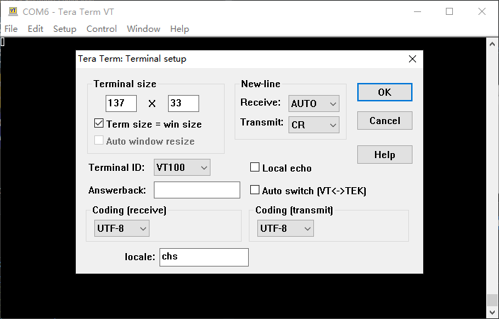
从“设置”>“终端”打开配置窗口并按如下方式更改设置。
-
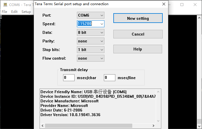
从“设置”>“串行端口”打开配置窗口,并按如下方式更改设置。
-
连接电源线给开发板上电,终端上会显示以下信息。
SCI Download mode (Normal SCI boot) -- Load Program to SRAM --------------- -
打开“文件”>“发送文件…”并发送 Flash Writer 文件 (*.mot) 作为文本。如果显示以下信息,则文件传输成功。
Flash writer for RZ/V2x Series Vx.xx xxx.xx,20xx Product Code : RZ/V2x > -
在终端上输入“XLS2”以获取以下消息。
> XLS2 ===== Qspi writing of RZ/V2x Board Command ============= Load Program to Spiflash Writes to any of SPI address. Program size & Qspi Save Address ===== Please Input Program Top Address ============ Please Input : H' -
输入“8101e00”。日志继续。
Please Input : H'8101e00 ===== Please Input Qspi Save Address === Please Input : H' -
输入“00000”。日志继续。
Please Input : H'00000 please send ! ('.' & CR stop load) -
出现“please send!”后,在终端软件中打开 File → Send file…,以文本方式发送 bl2_bp_spi-rzv2*.srec 文件。
-
如果出现如下提示清除数据的消息,请输入“y”。
SPI Data Clear(H'FF) Check : H'00000000-0000FFFF,Clear OK?(y/n) -
随后会显示以下日志。结束地址取决于 AI SDK 版本。
Write to SPI Flash memory. ======= Qspi Save Information ================= SpiFlashMemory Stat Address : H'00000000 SpiFlashMemory End Address : H'00036D17 =========================================================== -
在终端上输入“XLS2”以获取以下消息。
> XLS2 ===== Qspi writing of RZ/V2x Board Command ============= Load Program to Spiflash Writes to any of SPI address. Program size & Qspi Save Address ===== Please Input Program Top Address ============ Please Input : H' -
输入“00000”。日志继续。
Please Input : H'00000 ===== Please Input Qspi Save Address === Please Input : H' -
输入“60000”。日志继续。
Please Input : H'60000 please send ! ('.' & CR stop load) -
出现“please send!”后,在终端软件中打开 File → Send file…,以文本方式发送 fip-rzv2*.srec 文件。
-
如果出现如下提示清除数据的消息,请输入“y”。
SPI Data Clear(H'FF) Check : H'00000000-0000FFFF,Clear OK?(y/n) -
随后会显示以下日志。结束地址取决于 AI SDK 版本。
Write to SPI Flash memory. ======= Qspi Save Information ================= SpiFlashMemory Stat Address : H'00060000 SpiFlashMemory End Address : H'0011C2EE =========================================================== -
关闭开发板电源,将 Bootsel 开关切回默认启动模式,然后启动开发板。
-
¶ 擦除 eMMC
使用 SD 卡启动开发板,然后运行以下 dd 命令擦除 eMMC:
$ sudo dd if=/dev/zero of=/dev/mmcblk0 bs=1M status=noxfer
$ sync¶ 第三方载板
-
按如下方式编辑 Armbian 镜像中的 /boot/armbianEnv.txt,或 Yocto 镜像中的 /boot/env.txt:
overlay_prefix=bpi-ai2n-waveshare-jetson-io fdtfile=renesas/bananapi-ai2n-waveshare-jetson-io-a.dtbNOTE:
-
AI2N 硬件不支持 HDMI 和 DP。
-
JETSON-IO-BASE-A 使用 5V DC,而不是 12V。
-